Flowmålere
Flowmålere
In the landscape of industrial process control, the precise measurement of fluid movement is as critical as the monitoring of tank contents. While level measurement provides a snapshot of inventory and volume, flowmålere (flow meters) provide the dynamic data necessary for mass balance, billing, and process optimization. For engineers and plant managers, understanding the synergy between level and flow instrumentation is essential for maintaining a safe and efficient facility.
Industrial flowmålere are devices used to measure the volume or mass of a gas or liquid. They are foundational components in sectors ranging from wastewater treatment to chemical manufacturing. This guide explores the fundamental principles of flow measurement, selection criteria for various industrial environments, and the critical installation factors that ensure long-term accuracy.
Understanding Flow Measurement Principles
Before selecting a specific instrument, it is necessary to understand the physics governing different measurement technologies. Flowmålere are generally categorized by the physical principle they employ to derive flow rates.
Electromagnetic Flow Measurement
Electromagnetic flow meters operate based on Faraday’s Law of Induction. This principle states that a conductor moving through a magnetic field produces an electrical signal. In this application, the conductive liquid (such as water or acids) acts as the conductor. As the fluid flows through a magnetic field generated by the meter, it creates a voltage proportional to its velocity.
Because there are no moving parts or obstructions in the flow path, electromagnetic meters offer very low pressure drop and are highly resistant to wear. However, they require the fluid to have a minimum conductivity, typically greater than 5 μS/cm.
Ultrasonic Flow Measurement
Ultrasonic flowmålere utilize sound waves to determine velocity. There are two primary types:
1. Transit-time: These meters send ultrasonic pulses back and forth across the pipe. The pulse traveling with the flow moves faster than the one traveling against it. The time difference is used to calculate the flow rate. These are ideal for clean liquids.
2. Doppler: These meters rely on sound waves reflecting off particles or bubbles within the fluid. The frequency shift of the reflected wave indicates the velocity. These are preferred for slurries or aerated liquids.
Vortex Flow Measurement
Vortex meters utilize the Karman Vortex Street principle. When a fluid meets an obstruction (a bluff body) in the pipe, vortices are shed alternately on each side. The frequency of this vortex shedding is directly proportional to the flow velocity. These meters are robust and suitable for high-temperature applications, including steam measurement.
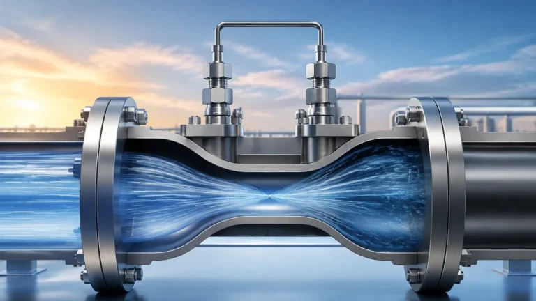
Differential Pressure (DP) Flow Measurement
DP meters create a deliberate constriction in the pipe (using an orifice plate, Venturi tube, or nozzle). By measuring the pressure difference before and after the constriction, the flow rate can be calculated using Bernoulli’s equation. While traditional, these systems require careful maintenance of the pressure sensing lines.
Selecting the Right Flowmålere for Your Application
Choosing the correct instrument requires a thorough analysis of the process media and the environmental conditions. The following table provides a comparison of common technologies used in industrial automation.
Technology Comparison Table
| Technology | Suitable Fluids | Accuracy (Typical) | Pressure Drop | Minimum Conductivity |
| :— | :— | :— | :— | :— |
| Electromagnetic | Conductive liquids, slurries | ±0.5% | Negligible | >5 μS/cm |
| Ultrasonic | Clean or aerated liquids | ±1.0% to ±2.0% | None | N/A |
| Vortex | Steam, gases, low-viscosity liquids | ±1.0% | Moderate | N/A |
| Turbine | Clean, low-viscosity liquids | ±0.25% to ±0.5% | High | N/A |
| Coriolis | Liquids, gases, high-viscosity fluids | ±0.1% | Moderate | N/A |
When evaluating these options, engineers must consider the Reynolds number of the flow. The Reynolds number is a dimensionless value that helps predict flow patterns (laminar vs. turbulent). Most flowmålere are designed to operate accurately within specific Reynolds number ranges, typically requiring turbulent flow for consistent performance.
For more comprehensive technical specifications and to see how these instruments integrate with level sensing systems, you can Review product options and application support on our Main Page.
Installation Considerations and Best Practices
Even the most advanced flowmålere will fail to provide accurate data if installed incorrectly. The goal of installation is to ensure a stable, fully developed flow profile as the fluid enters the measurement zone.
Straight Pipe Requirements
Most flow meters require a certain length of straight pipe both upstream and downstream of the sensor. This eliminates turbulence caused by elbows, valves, or pumps. A common rule of thumb is "10D upstream and 5D downstream," where D is the internal diameter of the pipe. For example, if using a 100 mm pipe, you would ideally have 1000 mm of straight pipe before the meter and 500 mm after it.
Orientation and Mounting
* Horizontal Pipes: For liquid applications, the meter should be installed in a way that ensures the pipe remains full. In horizontal runs, placing the meter at the lowest point of a "U" shape can prevent air pockets.
* Vertical Pipes: When measuring liquids in vertical pipes, the flow should always be upward. This ensures the pipe remains completely full and prevents the measurement of falling film or air gaps.
* Electrode Orientation: For electromagnetic meters, electrodes should be positioned horizontally (at the 3 o'clock and 9 o'clock positions) to prevent interference from sediment at the bottom or air at the top.
Grounding and Electrical Noise
Electromagnetic flowmålere are sensitive to electrical noise. Proper grounding is mandatory to ensure that the fluid and the sensor are at the same electrical potential. This usually involves grounding rings if the pipe is lined or made of non-conductive material like PVC.
Limitations and Environmental Factors
No single flow measurement technology is universal. Understanding the limitations is key to avoiding project failure.
1. Viscosity: High-viscosity fluids (like heavy oils or resins) can cause significant pressure drops and may transition from turbulent to laminar flow, affecting the accuracy of vortex and turbine meters.
2. Aeration and Cavitation: Bubbles in a liquid line can cause ultrasonic transit-time meters to lose signal and can lead to significant over-reading in electromagnetic meters.
3. Chemical Compatibility: The wetted parts of the meter (liners, electrodes, or bluff bodies) must be chemically resistant to the process media. Common materials include PTFE, PFA, and various stainless steel grades.
4. Ambient Conditions: Extreme temperatures or corrosive atmospheres in chemical plants can damage electronic transmitters. In such cases, remote-mounted electronics are recommended.
Synergizing Flow and Level Measurement
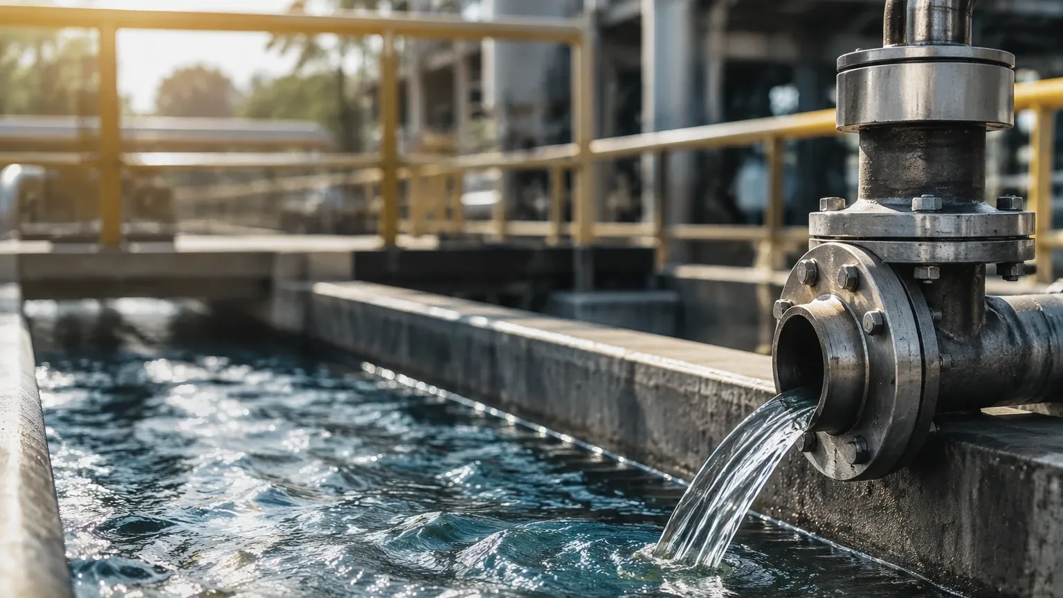
In many industrial applications, flowmålere and level meters work in tandem to provide a complete picture of the process. For instance, in a water treatment plant, an ultrasonic level sensor might monitor the height of water in a tank, while an electromagnetic flow meter tracks the effluent discharge.
By comparing the rate of change in the level (volume over time) with the flow rate reported by the flowmålere, operators can detect leaks or verify the calibration of the instruments. This redundancy is vital for environmental compliance and safety. Welk provides a range of level measurement solutions that complement these flow systems, ensuring that your Main Page for process data is always accurate and reliable.
Frequently Asked Questions (FAQ)
Q: How often should flowmålere be calibrated?
A: Calibration frequency depends on the application and the technology. For billing or regulatory compliance, annual calibration is standard. For general process monitoring, a check every two to three years may suffice unless a drift in data is observed.
Q: Can flowmålere measure two-phase flow (gas and liquid)?
A: Most standard flow meters struggle with two-phase flow. Coriolis meters are the most capable in these scenarios, but even they have limits. It is generally best to separate the phases before measurement.
Q: Do flowmålere require a specific power supply?
A: Most industrial meters operate on 24V DC (loop-powered or 4-wire) or 110/220V AC. Battery-powered versions are available for remote water applications where infrastructure is limited.
Q: What is the difference between mass flow and volumetric flow?
A: Volumetric flow measures the space the fluid occupies (e.g., liters per minute), which can change with temperature and pressure. Mass flow measures the actual weight of the fluid (e.g., kilograms per hour), which remains constant regardless of environmental changes. Coriolis meters measure mass flow directly.
Conclusion
Selecting and installing flowmålere requires a balance of theoretical knowledge and practical engineering. By understanding the measurement principles—whether electromagnetic, ultrasonic, or vortex—and adhering to strict installation guidelines regarding pipe runs and orientation, facilities can achieve high levels of process control. When integrated with reliable level measurement systems from providers like Welk, these instruments form the backbone of modern industrial automation. For further technical assistance and to explore our full range of measurement instrumentation, please visit our Main Page.