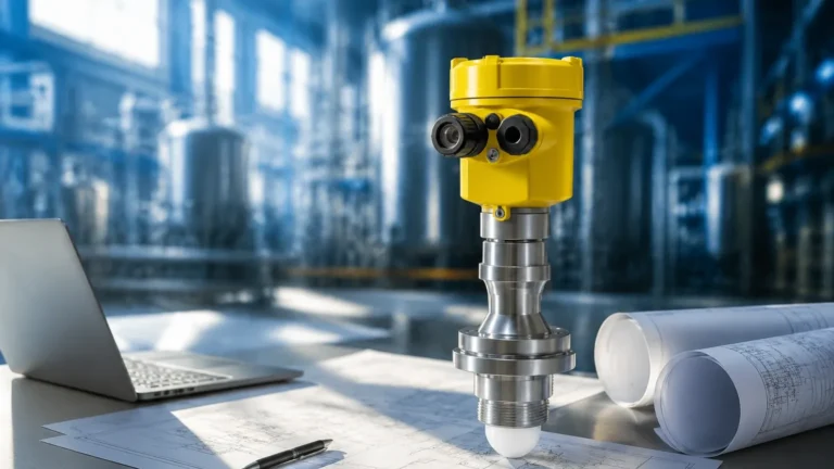
Clamp on Flow Meters
Clamp on Flow Meters
In the landscape of industrial process control, the ability to measure fluid velocity without interrupting operations or compromising the integrity of a piping system is a significant advantage. Clamp on flow meters, primarily utilizing ultrasonic technology, have emerged as a preferred solution for engineers seeking non-invasive, reliable, and cost-effective flow measurement. Unlike traditional inline meters that require pipe cutting and flange installation, these devices are mounted externally, offering a versatile alternative for both permanent installations and temporary diagnostic audits.
This guide explores the engineering principles, selection criteria, and practical installation considerations for clamp on flow meters, providing a technical foundation for their application across various industries such as water treatment, chemical processing, and oil and gas.
Understanding the Principles of Ultrasonic Flow Measurement
Clamp on flow meters operate based on ultrasonic wave propagation through the fluid. There are two primary measurement principles employed in these devices: Transit-Time and Doppler Effect. Understanding the difference between these two is critical for selecting the correct instrument for a specific application.
Transit-Time Ultrasonic Principle
Transit-time technology is the most common method used in modern industrial clamp on flow meters. It relies on the principle that an ultrasonic signal travels faster when moving in the direction of the fluid flow (downstream) than when moving against it (upstream).
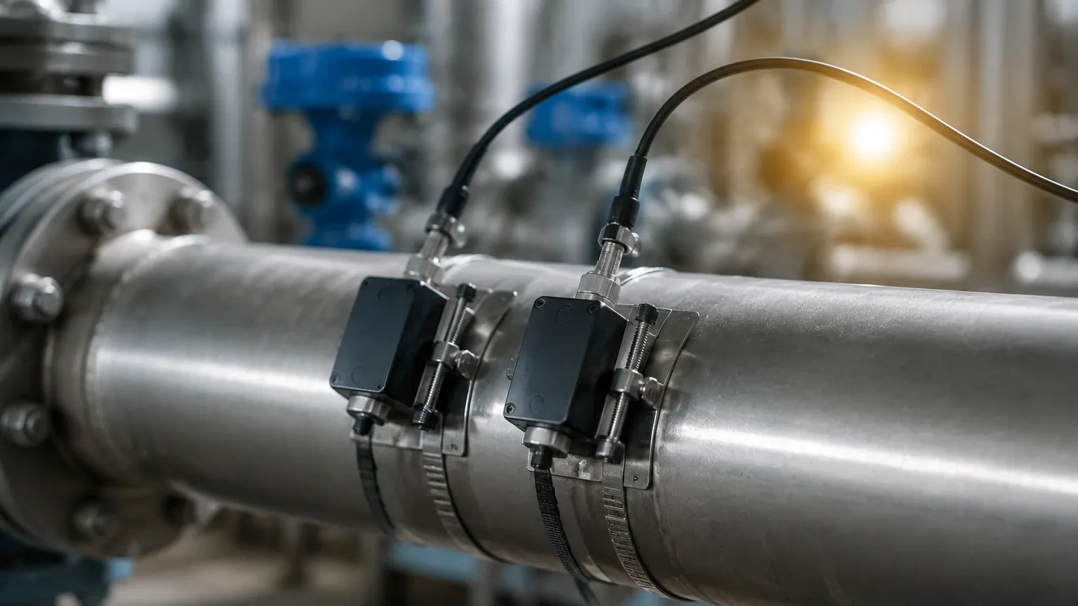
Two transducers are placed on the outside of the pipe, acting as both transmitters and receivers. They send ultrasonic pulses back and forth through the pipe wall and the moving liquid. The meter measures the time difference (delta-T) between the upstream and downstream transit times. This time difference is directly proportional to the flow velocity of the liquid. Once the velocity is determined, and the pipe's internal cross-sectional area is known (based on user-inputted pipe dimensions), the volumetric flow rate can be calculated with high precision.
Doppler Effect Principle
The Doppler Effect principle is used primarily for liquids containing suspended solids or entrained air bubbles. When an ultrasonic beam is transmitted into a moving fluid, the signal reflects off these particles or bubbles. Because the particles are moving, the frequency of the reflected signal is shifted (the Doppler shift) relative to the transmitted frequency. The flow meter measures this frequency shift to calculate the flow velocity. While generally less accurate than transit-time meters for clean liquids, Doppler meters are indispensable for slurries, wastewater, and aerated fluids where transit-time signals would be scattered or absorbed.
Key Evaluation Criteria for Selecting Clamp on Flow Meters
Selecting the appropriate clamp on flow meter requires a detailed analysis of the process environment and the physical characteristics of the piping system. Because the signal must pass through the pipe wall, the material and condition of the pipe are as important as the fluid itself.
Pipe Material and Condition
The acoustic properties of the pipe material dictate how well the ultrasonic signal penetrates. Common materials like carbon steel, stainless steel, copper, and most plastics (PVC, HDPE) are excellent conductors of ultrasound. However, materials with high internal damping or inconsistent structures, such as cast iron with heavy internal corrosion or concrete-lined pipes, can present challenges. If a pipe has an internal liner (e.g., rubber, cement, or epoxy), it is essential to ensure there is no air gap between the liner and the pipe wall, as air is a poor conductor of ultrasound and will block the signal.
Fluid Characteristics
For transit-time meters, the fluid should ideally be clean and free of significant solids or bubbles (typically less than 2% by volume). High concentrations of suspended solids can attenuate the signal, leading to measurement failure. Additionally, the fluid’s viscosity and temperature affect the speed of sound, which the meter must account for. Most high-quality meters include a database of fluid properties to automatically adjust these calculations.
Flow Profile and Straight Pipe Requirements
Like most flow measurement technologies, clamp on flow meters require a developed flow profile to achieve specified accuracy. This means the sensors should be installed on a straight section of pipe, away from turbulence-inducing elements like elbows, valves, pumps, and reducers. A general rule of thumb is to have 10 pipe diameters (10D) of straight pipe upstream and 5 pipe diameters (5D) downstream of the installation point.
Practical Selection Table: Transit-Time vs. Doppler
To assist in the initial engineering phase, the following table compares the two primary ultrasonic technologies based on application suitability.
| Feature | Transit-Time Ultrasonic | Doppler Effect Ultrasonic |
| :— | :— | :— |
| Primary Fluid Type | Clean liquids, deionized water, oils | Slurries, wastewater, aerated liquids |
| Suspended Solids | < 2% by volume | > 100 ppm (minimum particle size 100μm) |
| Typical Accuracy | ±0.5% to ±2.0% of reading | ±2.0% to ±5.0% of reading |
| Pipe Size Range | DN15 to DN6000 | DN25 to DN6000 |
| Installation | Non-invasive, clamp-on | Non-invasive, clamp-on |
| Flow Velocity Range | 0.01 to 12 m/s | 0.05 to 10 m/s |
| Sensitivity to Bubbles | High (can cause signal loss) | Low (required for measurement) |
Installation Guidelines and Best Practices
The accuracy of a clamp on flow meter is heavily dependent on the quality of the installation. Unlike inline meters, where the manufacturer controls the internal geometry, the user is responsible for the "meter body" (the pipe) in a clamp-on application.
1. Pipe Preparation
The exterior surface of the pipe where the transducers will be mounted must be cleaned thoroughly. Any loose paint, rust, or scale should be removed using a wire brush or sandpaper until the bare metal or smooth plastic surface is exposed. This ensures maximum acoustic coupling between the transducer and the pipe.
2. Transducer Mounting Modes
Depending on the pipe diameter and fluid properties, there are three common mounting configurations:
* V-Method: The signals bounce off the opposite pipe wall once. This is the standard method for pipe sizes ranging from DN25 to DN400. It provides a good balance between signal strength and path length.
* Z-Method: The transducers are mounted on opposite sides of the pipe, and the signal passes through the fluid only once. This is used for large pipes (above DN400) or pipes with high attenuation where signal strength is a concern.
* W-Method: The signal bounces three times before reaching the receiver. This is typically reserved for very small pipes (below DN25) to increase the transit time and improve resolution.
3. Coupling Agents
Because air gaps reflect almost 100% of ultrasonic energy, a coupling agent (acoustic gel or grease) must be applied between the transducer face and the pipe surface. For permanent installations, high-temperature silicone or specialized solid coupling pads are used to ensure the bond does not dry out or degrade over time.
4. Parameter Input
Modern meters require the user to input the pipe's outside diameter, wall thickness, material, fluid type, and liner thickness. The meter then calculates the exact distance (spacing) required between the two transducers. Measuring these parameters accurately is vital; for instance, a 1mm error in wall thickness input on a small pipe can lead to significant flow rate errors.
Common Risks and Technical Limitations
While clamp on flow meters offer significant advantages, engineers must be aware of potential pitfalls that can affect performance.
* Signal Attenuation: In very old pipes, internal scaling or heavy corrosion can scatter the ultrasonic signal. If the signal strength (often displayed as a percentage or decibel value on the meter) is too low, the measurement will be unstable.
* Empty or Partially Filled Pipes: Ultrasonic flow meters require a full pipe to function. If the pipe is partially full, the signal will not travel through the air space, and the meter will report an error. In such cases, level measurement instruments may be required to complement the flow data.
* Ambient Noise: In environments with heavy machinery, high-frequency mechanical vibrations can sometimes interfere with the ultrasonic signal. Using shielded cables and ensuring proper grounding of the transmitter can mitigate this risk.
* Temperature Extremes: Standard transducers typically operate up to 80°C or 120°C. For high-temperature applications (e.g., steam condensate or hot oil), specialized high-temperature transducers and mounting hardware are required to prevent damage to the piezoelectric elements.
Integrating Flow and Level Measurement in Industrial Applications
In many industrial processes, flow measurement is only one part of the equation. Comprehensive fluid management often requires the integration of both flow and level data. For example, in water treatment facilities, monitoring the flow rate into a reservoir using clamp on flow meters while simultaneously tracking the reservoir level using radar or ultrasonic level sensors allows for precise mass balance calculations and leak detection.
Welk, a professional manufacturer of industrial level measurement instruments, provides a range of solutions that complement flow monitoring systems. From radar level meters to hydrostatic transmitters, these instruments ensure that process operators have a complete picture of their fluid dynamics. For engineers seeking comprehensive instrumentation suites, including advanced radar and ultrasonic solutions, visiting the Main Page provides a detailed overview of available technologies and application support.
Frequently Asked Questions
Q: Can clamp on flow meters measure gas flow?
A: Most standard industrial clamp on meters are designed for liquids. While specialized ultrasonic gas flow meters exist, they require much higher signal amplification and specific transducer designs due to the low density of gases compared to liquids.
Q: How often do the transducers need to be re-greased?
A: For temporary or portable use, re-greasing is required for every new installation. For permanent installations, if a high-quality silicone coupling or solid pad is used, the coupling can last for several years without maintenance. However, it is good practice to check signal strength annually.
Q: Does the pipe pressure affect the measurement?
A: Generally, no. Ultrasonic flow measurement is independent of fluid pressure, provided the pressure is high enough to prevent cavitation or the formation of gas bubbles, which would interfere with the signal.
Q: Can I use a clamp on meter on a pipe with a liner?
A: Yes, provided the liner is well-bonded to the pipe wall. If there is an air gap between the pipe and the liner (common in some old slip-lined pipes), the ultrasonic signal will be blocked.
Q: What is the minimum flow velocity that can be measured?
A: Most modern transit-time meters can measure velocities as low as 0.01 m/s, making them excellent for detecting leaks or monitoring very slow processes.
Conclusion
Clamp on flow meters represent a mature and highly reliable technology for non-invasive fluid monitoring. By eliminating the need for process downtime and reducing installation costs, they provide a flexible solution for various industrial sectors. Success with these instruments depends on a thorough understanding of the measurement principles, careful consideration of pipe and fluid conditions, and adherence to strict installation protocols. When combined with accurate level measurement, these devices form the backbone of efficient and safe industrial process control.