Electric Flow Meter
Electric Flow Meter
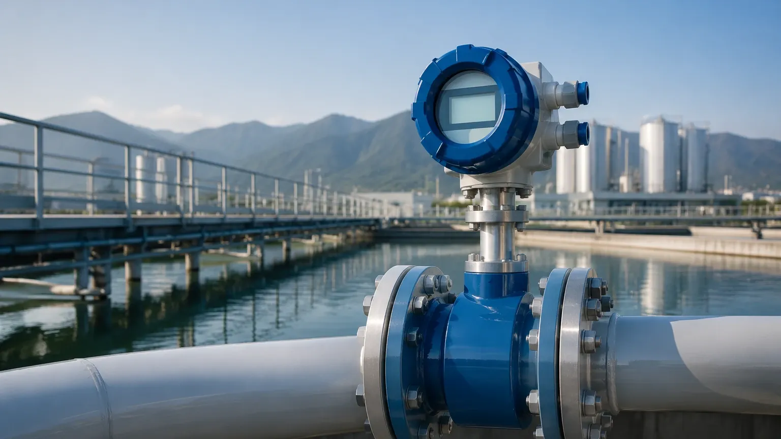
In modern industrial process control, the term "electric flow meter" typically refers to electromagnetic flow meters (often called magmeters) or advanced electronic flow measurement systems that utilize electrical properties to determine the velocity and volume of a fluid. These instruments are cornerstones of industrial automation, providing the high-precision data required to manage water treatment, chemical processing, and food production. As a professional manufacturer of industrial measurement instruments, Welk provides integrated solutions where level and flow data converge to optimize plant efficiency.
Understanding the technical nuances of electric flow meters is essential for engineers tasked with designing reliable process loops. This guide examines the measurement principles, selection criteria, and installation requirements necessary for successful deployment.
Operating Principles of Electromagnetic Flow Meters
The most common form of an electric flow meter is the electromagnetic flow meter. Its operation is based on Faraday's Law of Electromagnetic Induction. This principle states that a conductor moving through a magnetic field produces an electrical signal within the conductor, which is proportional to the velocity of the movement.
In the context of a flow meter:
1. The Magnetic Field: The meter body contains two electromagnetic coils that generate a constant magnetic field across the cross-section of the pipe.
2. The Conductor: The liquid flowing through the pipe acts as the conductor. For this to work, the liquid must have a minimum level of electrical conductivity (typically >5 μS/cm).
3. Induced Voltage: As the conductive liquid moves through the magnetic field, a voltage is induced. This voltage is picked up by two electrodes mounted on opposite sides of the pipe wall.
4. Calculation: The induced voltage ($E$) is directly proportional to the velocity of the fluid ($v$), the magnetic field strength ($B$), and the distance between the electrodes ($d$), expressed as $E = Bvd$. Since the cross-sectional area of the pipe is known, the electronics can instantly calculate the volumetric flow rate.
Because there are no moving parts in the flow path, electric flow meters of this type offer significant advantages in terms of pressure drop and maintenance requirements compared to mechanical meters.
Key Evaluation Criteria for Electric Flow Meters
Selecting the correct electric flow meter requires a thorough evaluation of the process fluid and the environmental conditions. Because these instruments rely on electrical signals, they are sensitive to the chemical and physical properties of the media.
Fluid Conductivity
Conductivity is the most critical factor. While most water-based liquids and acids are sufficiently conductive, hydrocarbons, oils, and distilled water often lack the necessary conductivity to generate a detectable signal. In such cases, alternative electronic technologies like ultrasonic flow meters may be required.
Liner and Electrode Material
The internal liner and the electrodes are the only parts in contact with the process fluid. Choosing the right material is vital for longevity and accuracy. Common liner materials include:
* PTFE/PFA: Excellent for high temperatures and aggressive chemicals.
* Hard Rubber/Neoprene: Suitable for water treatment and abrasive slurries.
* Polyurethane: Highly resistant to abrasion, ideal for mining applications.
Signal Output and Communication
Modern industrial facilities require seamless integration with PLC and SCADA systems. When evaluating an electric flow meter, confirm the availability of standard outputs such as 4-20mA, pulse/frequency, and digital protocols like HART, Modbus RS485, or Profibus. These allow for remote monitoring and integration with other instruments, such as those found on the Main Page of instrumentation providers.
Selection Guide and Technical Specifications
To assist in the selection process, the following table outlines common configurations for electric flow meters based on the application environment.
| Application Type | Recommended Liner | Electrode Material | Typical Accuracy |
| :— | :— | :— | :— |
| Potable Water | Hard Rubber / EPDM | Stainless Steel 316L | ±0.5% |
| Corrosive Acids | PTFE / PFA | Tantalum / Platinum | ±0.2% to ±0.5% |
| Abrasive Slurries | Polyurethane | Hastelloy C | ±0.5% |
| Food & Beverage | PFA (FDA Approved) | Stainless Steel 316L | ±0.25% |
| Wastewater | Neoprene | Ti (Titanium) | ±0.5% |
Velocity Limits
Most electric flow meters are designed to operate within a specific velocity range, typically between 0.3 m/s and 10 m/s (approx. 1 ft/s to 33 ft/s). Operating below 0.3 m/s can lead to signal noise and inaccuracy, while exceeding 10 m/s may cause excessive liner wear or cavitation.
Installation and Maintenance Guidelines
Proper installation is the single most important factor in ensuring the long-term accuracy of an electric flow meter. Even the most advanced instrument will fail to provide reliable data if installed incorrectly.
Pipe Orientation and Fill
The meter must always be full of liquid. If the pipe is only partially full, the meter will over-read or provide erratic data.
* Vertical Installation: This is the preferred orientation, with the flow moving upward. This ensures the pipe remains full and prevents the entrapment of air bubbles.
* Horizontal Installation: The meter should be installed in a low point of the piping system (a "U" section) to ensure it stays flooded. The electrodes should be positioned horizontally (at 3 and 9 o'clock) to prevent interference from sediment at the bottom or air at the top.
Straight Pipe Requirements
Turbulence caused by valves, pumps, or elbows can distort the flow profile. To achieve rated accuracy, maintain a minimum straight run of pipe:
* Upstream: 5 times the nominal diameter (5D).
* Downstream: 3 times the nominal diameter (3D).
If a valve is required, it should always be installed downstream of the flow meter to prevent cavitation and flow disturbance within the measurement zone.
Grounding
Since the meter measures millivolts of induced potential, electrical noise can easily corrupt the signal. Proper grounding is mandatory. If the piping is conductive (metal), the meter can be bonded to the flanges. If the piping is non-conductive (PVC or lined pipe), grounding rings must be installed to provide a path to the fluid and stabilize the reference potential.
Common Risks and Limitations
While electric flow meters are highly versatile, they are not universal solutions. Engineers should be aware of the following risks:
1. Entrained Air: Large bubbles or foam can interrupt the magnetic field and cause the meter to "zero out" or provide highly unstable readings. Air release valves should be installed upstream if air entrainment is likely.
2. Coating and Scaling: If the process fluid tends to leave deposits (e.g., lime scaling or oily films), the electrodes may become insulated from the fluid. Some advanced meters include "electrode cleaning" circuits, but manual cleaning may be necessary in extreme cases.
3. Vacuum Conditions: Certain liners, particularly PTFE, can collapse or pull away from the meter body if subjected to a vacuum. If vacuum conditions are possible, specified "vacuum-resistant" liners or PFA with stainless steel mesh reinforcement should be used.
4. Ambient Interference: High-power cables or large motors located in close proximity to the meter can create electromagnetic interference (EMI). Shielded cabling and dedicated conduits are recommended for signal transmission.
Frequently Asked Questions (FAQs)
Q: Can an electric flow meter measure steam or gases?
A: No. Electromagnetic flow meters require a conductive liquid. For steam or gas measurement, vortex or thermal mass flow meters are appropriate choices.
Q: Does the viscosity of the fluid affect the measurement?
A: Generally, no. As long as the flow is relatively laminar or stable and the fluid is conductive, viscosity changes do not affect the electromagnetic induction principle. However, extremely high viscosity may affect the flow profile and require longer straight pipe runs.
Q: How often should an electric flow meter be calibrated?
A: For most industrial applications, an annual verification is recommended. Many modern units offer "built-in verification" that checks the integrity of the coils and electronics without removing the meter from the line. Full wet calibration should be performed every 2-3 years or as dictated by regulatory requirements.
Q: What is the difference between an integral and a remote converter?
A: An integral converter is mounted directly on the flow sensor. A remote converter is connected via a cable and mounted in a more accessible location or a cleaner environment. Remote mounting is recommended for applications with high vibration, extreme temperatures, or where the sensor is installed in an inaccessible location.
By adhering to these engineering principles and selection criteria, facilities can ensure their flow measurement systems provide the accuracy and reliability required for complex industrial automation. For those integrating flow data with tank inventory systems, exploring the comprehensive range of sensors on the Main Page can provide a holistic view of process instrumentation needs.