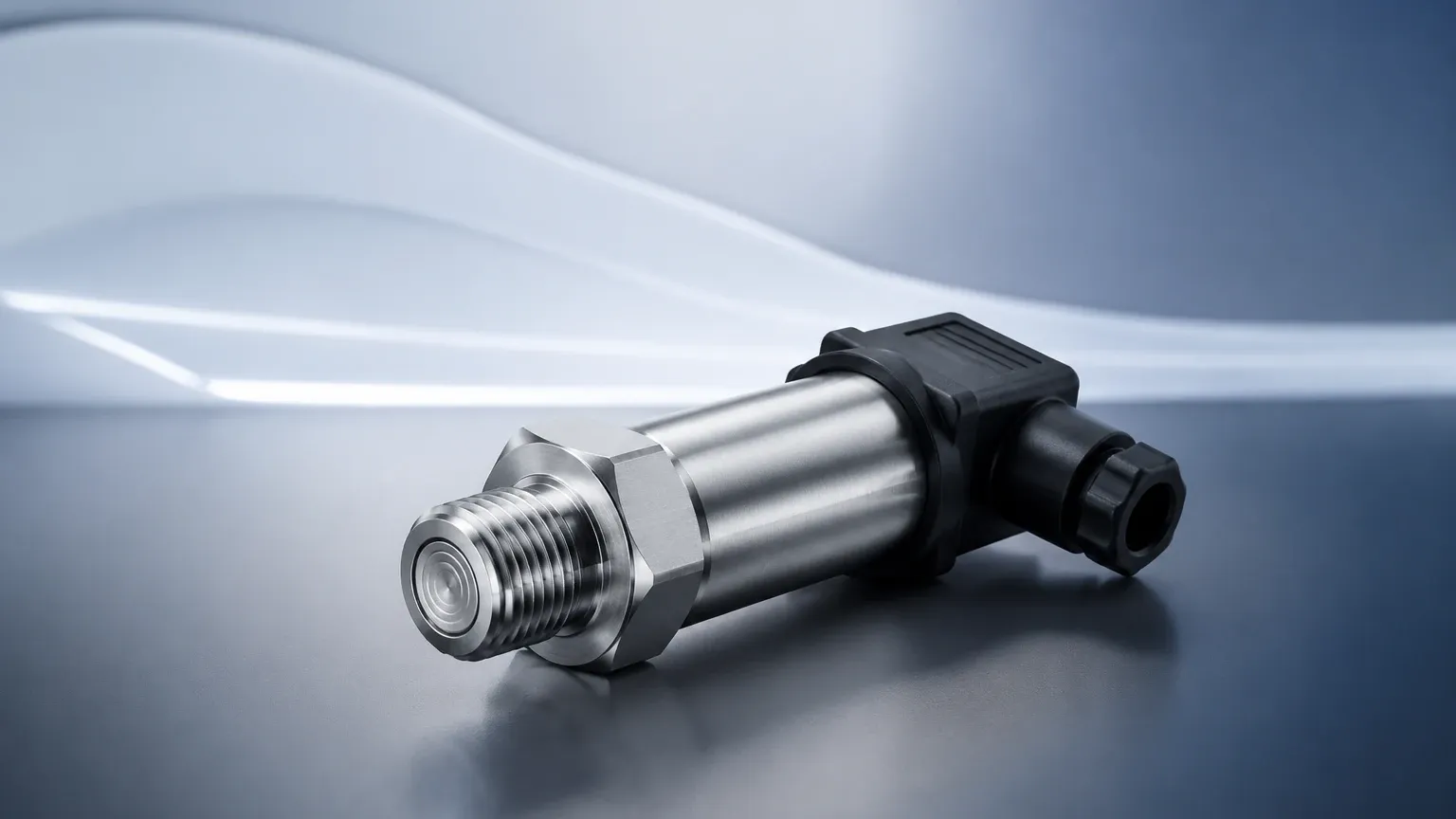
Pressure Sensor
Pressure Sensor
In the field of industrial automation and process control, the pressure sensor serves as a fundamental component for monitoring and managing fluid dynamics. While pressure measurement is a broad discipline, its application in level measurement—specifically through hydrostatic principles—is one of the most reliable and widely adopted methods across the water treatment, chemical, and oil and gas industries. This guide examines the technical foundations, selection criteria, and practical installation requirements for pressure sensors used in level detection.
The Principle of Hydrostatic Level Measurement
The most common use of a pressure sensor for level measurement is based on the hydrostatic principle. This principle states that the pressure at a specific point within a static liquid is directly proportional to the height of the liquid column above that point, provided the density of the liquid remains constant.
The Hydrostatic Formula
The relationship is defined by the mathematical formula:
P = ρ × g × h
Where:
* P is the hydrostatic pressure (measured in Pascals or bar).
* ρ (rho) is the density of the liquid (kg/m³).
* g is the acceleration due to gravity (approximately 9.81 m/s²).
* h is the height of the liquid column (meters).
Because gravity is a constant and the density of a specific process fluid is usually known, the pressure sensor can accurately calculate the liquid level by measuring the force exerted by the liquid. For example, in a water tank (density ≈ 1000 kg/m³), every 1 meter of water depth exerts approximately 9.81 kPa (0.098 bar) of pressure.
Core Sensor Technologies
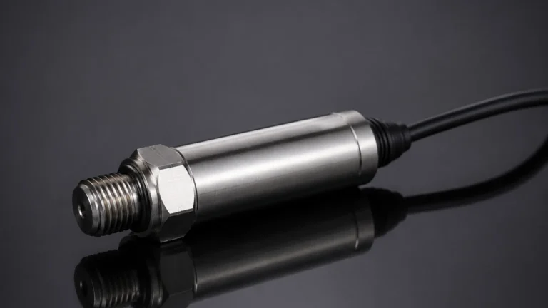
Modern industrial pressure sensors utilize different internal technologies to convert mechanical force into an electrical signal. The choice of technology impacts the sensor’s durability, accuracy, and compatibility with various chemical media.
1. Piezoresistive Silicon Sensors
These sensors utilize a silicon diaphragm with integrated strain gauges. When pressure is applied, the diaphragm deforms, changing the electrical resistance of the gauges. These are highly sensitive and cost-effective, making them ideal for clean water applications and general industrial use. However, because silicon is sensitive to harsh chemicals, these sensors often feature an isolated stainless steel diaphragm filled with silicone oil to transfer pressure to the sensing element.
2. Ceramic Capacitive Sensors
In a capacitive pressure sensor, a ceramic diaphragm acts as one plate of a capacitor. As pressure moves the diaphragm closer to a fixed ceramic substrate, the capacitance changes. Ceramic (typically 99.9% Alumina) is extremely hard and chemically inert, offering superior resistance to abrasion and corrosive chemicals. These are the preferred choice for wastewater, slurries, and aggressive acids where a stainless steel diaphragm might fail.
Classification of Pressure Sensors by Reference
When selecting a pressure sensor, it is critical to understand the pressure reference type, as this determines how the sensor accounts for atmospheric changes.
* Gauge Pressure (Relative): The sensor measures pressure relative to the current atmospheric pressure. This is the standard for vented or open-top tanks. A vent tube in the sensor cable allows the internal side of the diaphragm to "breathe," ensuring that changes in weather or altitude do not cause errors in level readings.
* Absolute Pressure: The sensor measures pressure relative to a perfect vacuum. These are used in specialized vacuum processes but are rarely used for standard level measurement unless paired with a second sensor to compensate for barometric pressure.
* Differential Pressure (DP): These sensors have two ports and measure the difference between them. This is essential for pressurized (closed) tanks, where the gas pressure above the liquid would otherwise be added to the hydrostatic pressure, resulting in a false high-level reading.
Selection Criteria for Industrial Applications
Choosing the right pressure sensor requires a thorough analysis of the process environment. The following table summarizes the primary considerations for different sensor configurations.
Selection Comparison Table
| Feature | Submersible Transmitter | Flange-Mounted Sensor | Differential Pressure (DP) |
| :— | :— | :— | :— |
| Primary Use Case | Deep wells, reservoirs, open tanks | Side-entry for large tanks | Pressurized vessels, boilers |
| Installation | Suspended by cable from top | Bolted to a side nozzle | Connected via impulse lines or seals |
| Maintenance | Easy to lift and clean | Requires tank to be drained or valved | Complex; requires manifold |
| Media Suitability | Clean water to wastewater | High-viscosity liquids | Gases and liquids |
| Max Temperature | Typically up to 80°C | Up to 200°C+ (with seals) | High temperature capable |
For engineers looking to compare specific models and technical performance data, the Main Page of the Welk product catalog provides comprehensive documentation on hydrostatic and radar-based solutions.
Installation Guidelines and Best Practices
Even the highest-quality pressure sensor will provide inaccurate data if installed incorrectly. Proper mechanical and electrical installation is the key to longevity.
1. Submersible Sensor Placement
* Avoid Turbulence: Do not install the sensor directly near an inlet pipe or agitator. The moving fluid creates dynamic pressure that the sensor will interpret as a fluctuating level. Use a stilling well (a perforated pipe) if the tank is turbulent.
* Cable Protection: The cable of a submersible pressure sensor contains a delicate vent tube. Ensure the cable is not kinked or crushed. The end of the cable should terminate in a junction box with a desiccant filter to prevent moisture from entering the vent tube and causing internal corrosion.
* Mounting Height: The sensor should be mounted at least 50 mm to 100 mm above the bottom of the tank to avoid being buried in settled sludge or sediment.
2. External/Flange Mounting
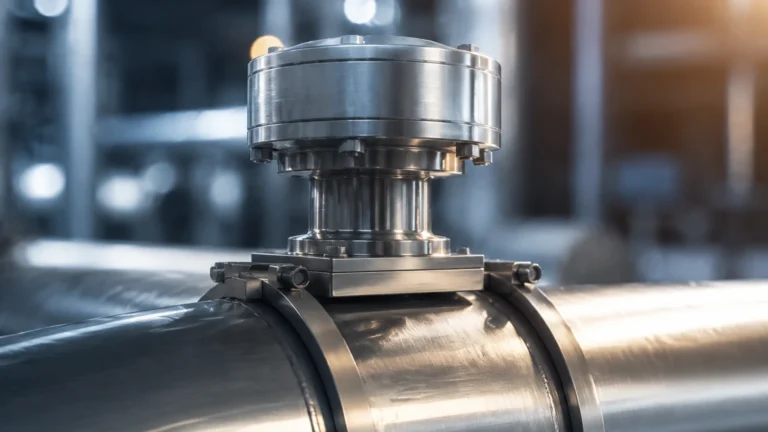
* Zero Point Calibration: When a sensor is mounted on the side of a tank, there is often a "dead zone" between the bottom of the tank and the sensor's center line. This offset must be programmed into the control system or the sensor's electronics to ensure the zero-level reading corresponds to the actual tank bottom.
* Isolation Valves: Always install a ball valve or needle valve between the tank nozzle and the sensor. This allows the sensor to be removed for calibration or cleaning without draining the entire vessel.
Limitations and Environmental Factors
While pressure-based level measurement is highly versatile, it has specific limitations that engineers must account for during the design phase:
* Density Sensitivity: Since the sensor measures weight, any change in fluid density will change the level reading. If a tank holds oil at 20°C and then the temperature rises to 60°C, the oil expands and its density drops. The pressure sensor will report a lower level even if the volume remains the same. In such cases, temperature compensation or an alternative technology like radar may be required.
* Clogging and Coating: In wastewater or paper pulp applications, solids can build up on the diaphragm. While ceramic sensors resist abrasion, a thick coating of grease or fibers will dampen the pressure signal and cause a "sluggish" response.
* Overpressure Events: Sudden pressure spikes (water hammer) can permanently deform a sensor diaphragm. It is vital to select a sensor with an overpressure rating at least 2 to 3 times the maximum expected operating pressure.
Maintenance and Troubleshooting
Regular maintenance ensures the accuracy of the pressure sensor over its typical 5-to-10-year lifespan.
1. Field Calibration: Sensors should be checked annually against a known reference (such as a manual dip tape or a portable pressure calibrator). Many modern transmitters support HART protocol, allowing for digital calibration without removing the device from the process.
2. Cleaning: For submersible units, gently wipe the diaphragm with a soft cloth. Never use a sharp object (like a screwdriver) to clear debris, as this will puncture the thin metal or ceramic sensing element.
3. Signal Drift: If the "zero" reading begins to climb over several months, it often indicates moisture ingress in the vent tube or the beginning of diaphragm fatigue.
Frequently Asked Questions (FAQ)
Q: Can a pressure sensor be used to measure the level of a foam-covered liquid?
A: Yes. Unlike ultrasonic or radar sensors, which may be confused by foam or vapor, a pressure sensor measures the mass of the liquid. It is unaffected by surface foam, making it an excellent choice for fermentation tanks or chemical mixers.
Q: What is the difference between a pressure sensor and a pressure transmitter?
A: In industrial terms, a "sensor" is the raw sensing element, while a "transmitter" includes the electronics that convert the signal into a standard industrial format, such as 4-20mA, Modbus, or Profibus.
Q: How do I handle level measurement in a tank that is under vacuum?
A: This requires a differential pressure sensor. One side of the sensor is connected to the bottom of the tank (liquid + vacuum pressure), and the other side is connected to the top of the tank (vacuum pressure only). The sensor subtracts the vacuum pressure, leaving only the hydrostatic liquid pressure.
Q: Is a pressure sensor suitable for high-viscosity liquids?
A: Yes, but a "flush diaphragm" design should be used. Standard sensors have a small pressure port that can easily clog with thick fluids. A flush diaphragm sits level with the process connection, preventing material buildup.
Conclusion
The pressure sensor remains a cornerstone of industrial level measurement due to its simplicity, reliability, and cost-effectiveness. By understanding the hydrostatic principle and carefully selecting the diaphragm material and reference type, engineers can implement robust level monitoring solutions in even the most challenging environments. For further technical guidance on selecting the appropriate instrument for your specific application, you may review product options and application support on the Main Page of our engineering resource site.