Flow Tester
Flow Tester
In industrial process automation and fluid management, a flow tester is an essential diagnostic and monitoring instrument used to quantify the movement of liquids, gases, or steam through a conduit or open channel. While often categorized alongside flow meters, a flow tester specifically serves the purpose of verifying system performance, calibrating existing installations, or providing temporary measurement in field conditions. For engineers and plant managers, selecting the correct flow testing technology is a prerequisite for maintaining operational efficiency, ensuring safety, and meeting regulatory requirements in sectors such as water treatment, chemical processing, and oil and gas.
Understanding the relationship between level measurement and flow measurement is critical. In many industrial scenarios, particularly in open channel applications or tank discharge monitoring, level measurement instruments—such as those found on the Welk Main Page—function as the primary sensing element for flow calculation. This guide explores the principles, selection criteria, and practical applications of flow testing technologies.
Measurement Principles of Flow Testing
Before selecting a flow tester, it is necessary to understand the underlying physical principles that govern how these devices interact with the media. Flow testing generally falls into two categories: closed-pipe measurement and open-channel measurement.
1. Ultrasonic Transit-Time Principle
Ultrasonic flow testers are among the most versatile tools for non-invasive testing. They utilize two transducers clamped to the outside of a pipe. The device sends and receives ultrasonic pulses between the transducers. When the fluid is moving, the pulse traveling in the direction of the flow moves faster than the pulse traveling against it. The difference in time (transit-time) is directly proportional to the fluid velocity. This method is ideal for clean liquids and provides high accuracy without interrupting the process.
2. Radar and Ultrasonic Level-to-Flow Conversion
In open channels, such as flumes or weirs, a flow tester often utilizes non-contact level measurement. By mounting an ultrasonic or radar level sensor above the water surface, the instrument measures the "head" (the height of the liquid). Since the geometry of the weir or flume is known, the flow rate (Q) can be calculated using established mathematical formulas (e.g., Q = C × Hⁿ). This is a standard approach in wastewater treatment and irrigation systems.
3. Differential Pressure (DP) Principle
This traditional method involves placing a restriction in the flow path, such as an orifice plate or Venturi tube. As fluid passes through the restriction, its velocity increases and its pressure decreases. A flow tester measures the pressure difference between the upstream and downstream sides. The square root of this pressure differential is proportional to the flow rate. While reliable, this method introduces a permanent pressure loss to the system.
4. Hydrostatic Pressure for Flow Verification
In specific tank-emptying applications, hydrostatic level transmitters can act as a flow tester by monitoring the rate of change in level over time (dV/dt). By calculating the volume change relative to the time elapsed, operators can verify the discharge rate of pumps or gravity-fed systems.
The Relationship Between Level and Flow Testing
In many B2B industrial environments, flow testing is inextricably linked to level measurement. For example, in a chemical storage facility, a radar level meter monitors the inventory. If the facility needs to test the flow rate of a transfer pump, the radar sensor's data can be integrated into a PLC (Programmable Logic Controller) to determine the flow based on the decreasing level in the source tank.
Welk’s range of industrial level measurement instruments, including radar level meters and ultrasonic sensors, provides the foundational data required for these flow calculations. Accurate level data ensures that the derived flow rates remain within the required ±0.5% to ±1.0% accuracy range for most industrial benchmarks.
Key Evaluation Criteria for Flow Testers
When evaluating a flow tester for a specific application, engineers must look beyond the basic price point and consider the long-term operational environment. The following criteria are essential:
* Media Characteristics: Is the fluid conductive? Does it contain solids or air bubbles? For example, magnetic flow testers require conductive liquids, while ultrasonic Doppler testers require a certain percentage of particles or bubbles to reflect the signal.
* Pipe Diameter and Material: For clamp-on ultrasonic testers, the pipe material (e.g., carbon steel, PVC, stainless steel) and wall thickness must be known to calibrate the signal path correctly. Standard industrial ranges often span from DN15 (1/2 inch) to DN3000 (120 inches).
* Installation Constraints: Does the application allow for cutting the pipe, or is a non-invasive solution required? Portable flow testers are almost exclusively non-invasive to allow for rapid deployment across different points in a plant.
* Accuracy Requirements: Laboratory-grade flow testing might require 0.2% accuracy, whereas general process monitoring might suffice with 1.0% to 2.0%.
Selection Table: Flow Testing Technologies
| Technology | Typical Accuracy | Media Type | Installation | Best Use Case |
| :— | :— | :— | :— | :— |
| Ultrasonic (Clamp-on) | ±0.5% – 2.0% | Clean Liquids | Non-invasive | Field audits, pump performance testing |
| Radar (Non-contact) | ±1mm (Level) | Any Liquid | Above Media | Open channel flow, wastewater weirs |
| Electromagnetic | ±0.2% – 0.5% | Conductive Liquids | Inline | Chemical dosing, water distribution |
| Hydrostatic | ±0.1% – 0.25% | Liquids | Bottom-mounted | Tank discharge flow verification |
| Vortex | ±1.0% | Steam, Gas, Liquid | Inline | High-temperature steam flow testing |
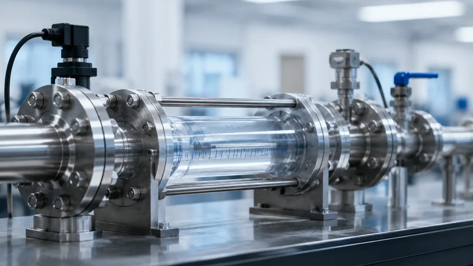
Installation Considerations and Best Practices
Proper installation is the single most important factor in the reliability of a flow tester. Even the most advanced sensor will provide inaccurate data if the hydraulic conditions are poor.
1. Straight Pipe Runs: To ensure a stable velocity profile, flow testers typically require a minimum of 10 diameters (10D) of straight pipe upstream and 5 diameters (5D) downstream from any elbows, valves, or pumps. If these requirements are not met, turbulence can cause significant measurement errors.
2. Full Pipe Requirement: For closed-conduit testers, the pipe must be completely full of liquid. In horizontal pipes, sensors should be mounted at the 3 o'clock or 9 o'clock positions to avoid air pockets at the top and sediment at the bottom.
3. Signal Coupling: For ultrasonic flow testers, a coupling agent (grease or gel) must be applied between the transducer and the pipe surface to eliminate air gaps that would otherwise block the high-frequency sound waves.
4. Environmental Shielding: For radar or ultrasonic level-based flow testers in outdoor open channels, sunshields should be used to prevent temperature fluctuations from affecting the electronics or the speed of sound (in the case of ultrasonic sensors).
Limitations and Common Risks
While modern flow testers are highly robust, they are not without limitations. Recognizing these risks early can prevent costly errors in data collection.
* Scaling and Buildup: In chemical or wastewater applications, the internal buildup of minerals or biological matter can change the internal diameter of the pipe. Since flow testers calculate volume based on the programmed diameter, scaling leads to an overestimation of flow.
* Signal Interference: High-frequency vibration from nearby heavy machinery or electromagnetic interference (EMI) from variable frequency drives (VFDs) can corrupt the signal of electronic flow testers. Proper grounding and shielded cabling are mandatory.
* Fluid Homogeneity: If a liquid is not well-mixed or contains varying concentrations of gas, the density and sound-velocity profile change, which can lead to erratic readings in mass flow or ultrasonic testers.
Frequently Asked Questions (FAQ)
Q: Can a level meter be used as a flow tester for all tanks?
A: No. A level meter can only be used as a flow tester if the tank's cross-sectional area is known and constant, or if there is a standardized discharge structure (like a weir) where the relationship between level and flow is mathematically defined.
Q: How often should a portable flow tester be calibrated?
A: For most industrial B2B applications, annual calibration is recommended. However, if the tester is used for regulatory compliance or high-value custody transfer, semi-annual calibration may be required.
Q: Why is my ultrasonic flow tester showing a "Low Signal" error?
A: This is usually caused by poor transducer coupling, a pipe that is not full, or excessive lining thickness (such as thick cement-lined ductile iron) that absorbs the ultrasonic signal.
Q: Does temperature affect flow testing?
A: Yes. Temperature affects fluid density and viscosity. Most advanced flow testers include temperature compensation features to adjust the calculations in real-time.
Conclusion
A flow tester is more than just a measurement device; it is a critical component of industrial diagnostic infrastructure. Whether utilizing non-invasive ultrasonic technology for pipe audits or leveraging high-precision radar level sensors for open-channel flow monitoring, the goal remains the same: obtaining accurate, repeatable data to drive process optimization. By adhering to strict installation guidelines and selecting technology based on the specific physical properties of the media, engineers can ensure their flow testing regimes provide the reliability required for modern industrial automation. For those seeking specific hardware solutions, reviewing the technical specifications of radar and ultrasonic transmitters on the Welk Main Page is a recommended next step in the selection process.