How Ultrasonic Flow Meter Works
How Ultrasonic Flow Meter Works
In the realm of industrial process control and automation, the ability to measure fluid movement without interrupting the flow or compromising the integrity of the piping system is a significant advantage. Ultrasonic flow meters have emerged as a premier solution for these requirements. As a specialized manufacturer of industrial measurement instruments, Welk provides a range of sensing technologies designed for accuracy and reliability in demanding environments. Understanding how ultrasonic flow meter works is essential for engineers and plant managers tasked with selecting the right instrumentation for water treatment, chemical processing, and oil and gas applications.
Unlike mechanical flow meters that rely on moving parts—which are prone to wear and pressure drops—ultrasonic meters utilize sound waves to determine the velocity of a liquid. This non-invasive approach reduces maintenance costs and extends the operational lifespan of the measurement system.
Measurement Principles: Transit-Time vs. Doppler
To understand how ultrasonic flow meter works, one must first distinguish between the two primary physical principles used in the industry: Transit-Time and Doppler Effect. The choice between these two depends entirely on the characteristics of the fluid being measured.
1. Transit-Time Principle
Transit-time ultrasonic flow meters are the most common type used in industrial applications, particularly for clean liquids. This method relies on the difference in the time it takes for an ultrasonic pulse to travel between two transducers.
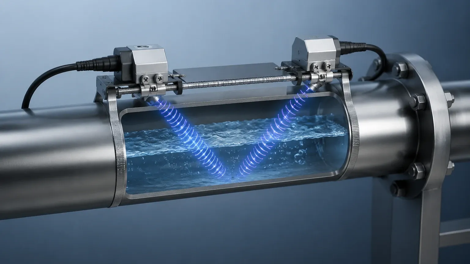
One transducer transmits a signal downstream, while the other transmits a signal upstream. Sound waves traveling with the flow move faster, while those traveling against the flow move slower. The meter measures this minute time difference (often in nanoseconds). This difference is directly proportional to the velocity of the fluid. Once the velocity is known, the meter calculates the volumetric flow rate based on the cross-sectional area of the pipe.
2. Doppler Effect Principle
The Doppler flow meter operates on the principle of frequency shift. It requires the presence of "reflectors" within the liquid, such as suspended solids or entrained gas bubbles.
When an ultrasonic beam is transmitted into the moving fluid, the sound waves reflect off these particles. Because the particles are moving, the frequency of the reflected signal is shifted (the Doppler effect). The meter measures this frequency shift to determine the flow velocity. This technology is ideal for slurries, wastewater, and aerated liquids where transit-time signals would be scattered or absorbed.
How Ultrasonic Flow Meter Works: A Technical Breakdown
At the core of the device are piezoelectric transducers. These components convert electrical energy into mechanical vibrations (ultrasonic sound waves) and vice versa. When an electrical pulse is applied to the transducer, it vibrates at a high frequency—typically between 0.5 MHz and 4 MHz—sending a wave through the pipe wall and into the fluid.
The Calculation Process
For a transit-time meter, the mathematical relationship is defined by the following variables:
- L: The distance between transducers.
- θ: The angle of the ultrasonic path relative to the flow.
- t_up: Time for the signal to travel upstream.
- t_down: Time for the signal to travel downstream.
The fluid velocity (v) is calculated using the formula:
`v = (L / 2cosθ) * ((t_up – t_down) / (t_up * t_down))`
Modern digital signal processing (DSP) allows these meters to filter out background noise and pipe vibrations, ensuring that only the relevant ultrasonic signals are used for calculation. For those integrating these sensors into broader automation frameworks, reviewing the various product options on the Main Page can help identify the specific communication protocols (such as Modbus or 4-20mA) required for your system.
Hardware Configurations: Inline vs. Clamp-on
How an ultrasonic flow meter works in a practical setting is also influenced by its physical installation. There are two primary hardware configurations used in industrial automation.
Inline Ultrasonic Flow Meters
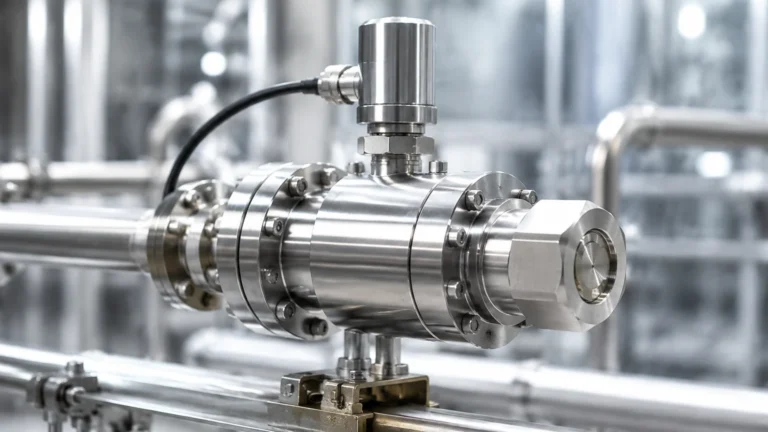
Inline meters are integrated directly into the piping system via flanges or threaded connections. The transducers are "wetted," meaning they are in direct contact with the fluid.
- Pros: Highest accuracy (often up to ±0.5%), factory-calibrated as a complete unit, and capable of measuring very low flow rates.
- Cons: Requires pipe cutting for installation and process downtime.
Clamp-on Ultrasonic Flow Meters
Clamp-on meters are mounted to the exterior of the pipe. The ultrasonic signal must pass through the pipe wall, the coupling acoustic gel, and then the fluid.
- Pros: No process downtime, no risk of leaks or contamination, and highly portable for site audits.
- Cons: Accuracy is slightly lower (typically ±1% to ±3%) and is sensitive to pipe material and wall thickness.
Selection Criteria for Industrial Applications
Choosing the correct meter requires a detailed analysis of the process conditions. Use the following table as a preliminary guide for technology selection.
| Feature | Transit-Time (Clean Liquids) | Doppler (Dirty Liquids) |
| :— | :— | :— |
| Fluid Type | Potable water, oils, chemicals, deionized water | Wastewater, slurries, aerated liquids, pulp stock |
| Particle Concentration | < 2% by volume | > 100 ppm of particles/bubbles (>100 microns) |
| Typical Accuracy | ±0.5% to ±1.0% | ±2.0% to ±5.0% |
| Pipe Size Range | 15 mm to 6000 mm | 25 mm to 6000 mm |
| Flow Velocity Range | 0.01 m/s to 12 m/s | 0.1 m/s to 10 m/s |
| Maintenance | Very Low | Low |
Installation Considerations and Best Practices
Even the most advanced ultrasonic meter will fail to provide accurate data if installed incorrectly. Because the meter calculates flow based on a velocity profile, the fluid must be "fully developed" and laminar.
1. Straight Pipe Runs
To avoid turbulence caused by valves, pumps, or elbows, specific straight-run requirements must be met:
- Upstream: Minimum of 10 times the pipe diameter (10D).
- Downstream: Minimum of 5 times the pipe diameter (5D).
If a pump is located upstream, the requirement may increase to 30D or more.
2. Transducer Mounting Methods
For clamp-on meters, the path of the sound wave determines the mounting configuration:
- V-Method: The signal bounces once off the opposite pipe wall. This is the standard for pipes ranging from 25 mm to 400 mm (1" to 16").
- Z-Method: Transducers are mounted on opposite sides of the pipe. The signal crosses once. This is used for large pipes (over 400 mm) or where the fluid is slightly attenuating.
- W-Method: The signal bounces three times. This is used for very small pipes (under 50 mm) to increase the transit time and improve resolution.
3. Acoustic Coupling
For clamp-on installations, an acoustic couplant (grease or gel) must be applied between the transducer face and the pipe surface. This eliminates air gaps that would otherwise reflect the ultrasonic energy before it enters the pipe.
Limitations and Operational Challenges
While ultrasonic technology is versatile, it is not a "one-size-fits-all" solution. Engineers must be aware of the following limitations:
* Pipe Material: Materials with high acoustic damping, such as certain plastics or lined pipes (e.g., concrete-lined or rubber-lined), can weaken the signal. The liner must be well-bonded to the pipe wall; any air gap between the liner and the pipe will stop the signal entirely.
* Aeration and Solids (for Transit-Time): If a transit-time meter is used on a fluid with excessive bubbles or solids, the signal will be scattered, leading to a "signal loss" error.
* Temperature Extremes: High-temperature fluids require specialized transducers and mounting hardware to prevent damage to the piezoelectric elements.
* Flow Profile: Non-full pipes cannot be measured accurately by standard ultrasonic flow meters. The pipe must be 100% full to ensure a consistent acoustic path.
Frequently Asked Questions (FAQs)
Q: Can ultrasonic flow meters measure gas flow?
A: Yes, but gas flow measurement requires much higher frequency transducers and specialized signal processing because gas is significantly less dense than liquid, making sound transmission more difficult. Most standard industrial ultrasonic meters are optimized for liquids.
Q: How does pipe scaling affect the measurement?
A: Internal scaling or build-up changes the internal diameter (ID) of the pipe. Since the meter calculates volumetric flow based on the programmed ID, scaling will cause the meter to over-read. In clamp-on applications, heavy scaling can also attenuate the ultrasonic signal.
Q: Do ultrasonic flow meters require periodic recalibration?
A: Because there are no moving parts to wear out, ultrasonic meters are extremely stable. However, for regulated industries (like water billing or chemical dosing), annual verification or calibration is recommended to ensure the electronics and transducers are performing within spec.
Q: What is the minimum conductivity required for ultrasonic measurement?
A: Unlike electromagnetic flow meters, ultrasonic meters do not require the fluid to be conductive. They work perfectly on non-conductive liquids like distilled water, hydrocarbons, and alcohols.
Conclusion
Understanding how ultrasonic flow meter works allows industrial operators to leverage a non-invasive, highly accurate, and low-maintenance measurement solution. By selecting the appropriate principle—transit-time for clean fluids or Doppler for reflective fluids—and adhering to strict installation guidelines regarding straight pipe runs and acoustic coupling, facilities can achieve reliable process control.
Welk continues to support the global industrial sector with robust measurement technologies. For more information on integrating these sensors into your specific application or to explore our wider range of level and flow instrumentation, please refer to our Main Page for technical specifications and engineering support.