Raman Spectroscopy System
Raman Spectroscopy System
In the landscape of industrial process control, the ability to identify chemical compositions in real-time has become as critical as measuring physical parameters like pressure, temperature, and volume. A Raman spectroscopy system serves as a sophisticated analytical tool that provides a "molecular fingerprint" of substances without requiring direct contact or destructive sampling. For engineers managing complex chemical reactors, water treatment facilities, or oil and gas refineries, integrating Raman spectroscopy with traditional instrumentation—such as those found on our Main Page—offers a comprehensive view of both the quantity and quality of the materials within a vessel.
This article examines the technical foundations of Raman spectroscopy, the components that constitute a robust industrial system, and the practical considerations for selecting and installing these instruments in demanding process environments.
Measurement Principles of Raman Spectroscopy
To effectively implement a raman spectroscopy system, one must first understand the underlying physics of light-matter interaction. When a high-intensity monochromatic light source (typically a laser) illuminates a sample, the majority of the photons are scattered elastically. This is known as Rayleigh scattering, where the scattered light has the same frequency as the incident light.
However, a tiny fraction of the light—approximately one in every ten million photons—undergoes inelastic scattering. This phenomenon, discovered by C.V. Raman in 1928, involves an energy exchange between the incident photons and the vibrational or rotational energy levels of the molecules in the sample.
The Raman Shift
If the scattered photon loses energy to the molecule, it emerges at a lower frequency (longer wavelength), known as Stokes scattering. Conversely, if the photon gains energy from a molecule already in an excited vibrational state, it emerges at a higher frequency (shorter wavelength), known as Anti-Stokes scattering. The difference in energy between the incident and scattered light is called the "Raman shift," usually measured in wavenumbers (cm⁻¹). Because every chemical bond has unique vibrational frequencies, the resulting spectrum provides a precise identification of the molecular structure.
Core Components of an Industrial Raman Spectroscopy System
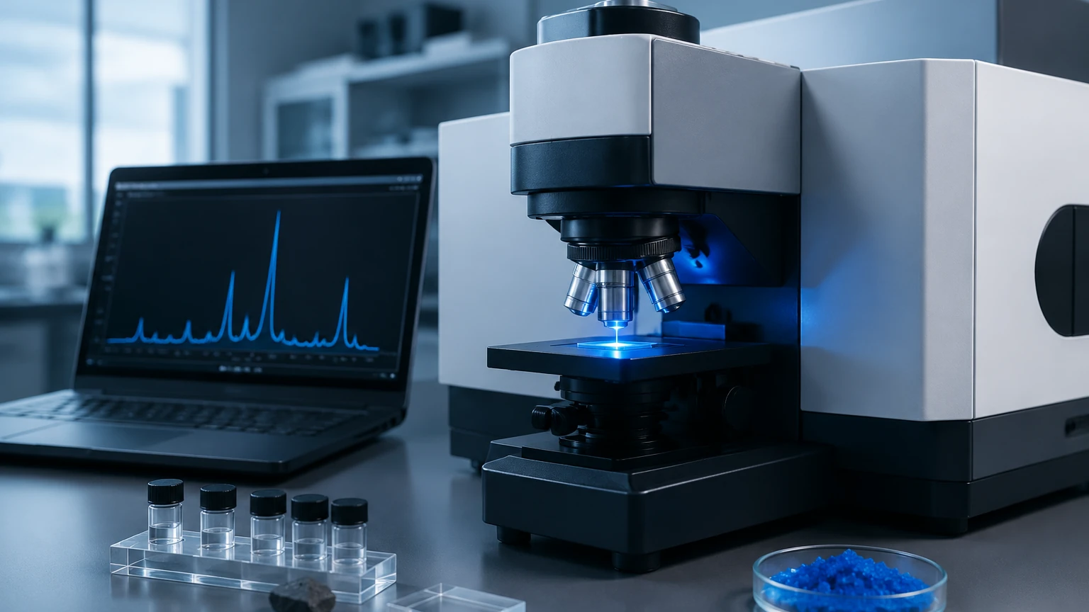
A modern industrial Raman spectroscopy system is comprised of four primary functional blocks, each optimized for stability and accuracy in a 24/7 production environment.
1. The Excitation Source (Laser)
The laser provides the monochromatic light necessary for excitation. In industrial settings, the choice of wavelength is a balance between signal strength and background interference. Shorter wavelengths (e.g., 532 nm) produce stronger Raman signals but are more likely to trigger fluorescence, which can overwhelm the detector. Longer wavelengths (e.g., 1064 nm) minimize fluorescence but require more sensitive detectors and higher power to achieve a usable signal.
2. The Sampling Interface
Unlike laboratory systems, industrial Raman systems often use fiber-optic probes to reach the sample. These probes are designed to withstand high pressures (up to 300 bar) and extreme temperatures. The interface typically features a sapphire window, chosen for its chemical inertness and extreme hardness, allowing the laser to pass into the process fluid while maintaining a hermetic seal.
3. The Spectrograph and Filter System
Before the scattered light reaches the detector, the intense Rayleigh scattering must be filtered out using a notch or edge filter. The remaining Raman-shifted light is then dispersed by a diffraction grating within the spectrograph, separating the light into its constituent wavelengths.
4. The Detector
Most industrial systems utilize a Charge-Coupled Device (CCD) or an Indium Gallium Arsenide (InGaAs) array. These detectors are often thermoelectrically cooled to reduce thermal noise, ensuring that even the weak Raman signals are captured with high precision.
Evaluating Raman Spectroscopy Systems: Selection Criteria
Choosing the right system requires matching the optical specifications to the specific process requirements. The following table provides a comparison of common configurations based on the laser wavelength:
| Feature | 532 nm Laser | 785 nm Laser | 1064 nm Laser |
| :— | :— | :— | :— |
| Primary Use Case | Inorganic materials, carbon nanotubes | General chemical analysis, polymers | Heavily fluorescing samples, oils |
| Signal Intensity | Very High | High | Low |
| Fluorescence Risk | High | Moderate | Very Low |
| Detector Type | Silicon CCD | Silicon CCD | InGaAs Array |
| Cooling Required | Minimal | Moderate | High |
| Typical Applications | Water treatment, minerals | Pharmaceutical, Specialty Chem | Petrochemical, Bio-fuels |
Beyond wavelength, engineers must consider the spectral resolution. For simple identification, a resolution of 10–15 cm⁻¹ may suffice. However, for distinguishing between similar isomers or monitoring subtle stress changes in crystals, a high-resolution system ( < 4 cm⁻¹) is necessary.
Synergy with Level Measurement and Process Automation
In the context of industrial automation, a raman spectroscopy system does not operate in isolation. It is part of a broader suite of instruments that includes radar level meters, ultrasonic sensors, and pressure transmitters. While a radar level meter provides the physical height of a liquid in a tank, the Raman system provides the concentration of the reactants or the purity of the final product.
For example, in a chemical blending tank, a hydrostatic level transmitter ensures the tank does not overflow, while the Raman probe monitors the mixing ratio in real-time. This integration allows for "closed-loop" control, where the feed pumps are adjusted based on both the volume (level) and the chemical composition (Raman). For more information on integrating these physical measurement technologies, you can review product options and application support on our Main Page.
Installation and Application Engineering
Successful deployment of a Raman system in a B2B industrial environment requires careful attention to the physical installation and the environmental conditions.
Probe Placement and Fouling
The sampling probe should be installed in a location with representative flow, such as a bypass loop or a turbulent section of a pipe. In stagnant areas, sediment may accumulate on the sapphire window, leading to signal degradation. Many industrial probes now include "air-purge" or mechanical cleaning mechanisms to mitigate fouling in high-viscosity or slurry applications.
Fiber Optic Management
Because the spectrograph is often located in a controlled environment (like a rack room) while the probe is in the field, fiber optic cables are used for signal transmission. These cables must be protected by ruggedized conduits. It is important to note that signal loss occurs over long distances; typically, fiber runs are limited to 100 meters (approx. 328 feet) to maintain signal integrity, though specialized low-loss fibers can extend this range.
Hazardous Area Compliance
In oil and gas or chemical plants, the Raman system must comply with ATEX, IECEx, or NEC standards. Since the laser itself is a source of energy, the probe and the laser housing must be certified as intrinsically safe or explosion-proof. Laser safety is also paramount; industrial Raman systems are often classified as Class 1 systems during normal operation because the laser is fully enclosed within the process piping.
Limitations and Risks
Despite its versatility, a raman spectroscopy system has specific limitations that must be addressed during the engineering phase:
1. Fluorescence Interference: Some organic compounds and impurities emit a broad fluorescence signal that is much stronger than the Raman signal. This can be mitigated by changing the laser wavelength or using time-gated detection.
2. Sample Heating: High-power lasers can locally heat the sample, potentially causing thermal degradation or phase changes. This is particularly relevant for dark-colored or opaque samples that absorb light energy.
3. Sensitivity Limits: Raman is generally not a "trace analysis" technique. It is best suited for components present at concentrations above 0.1% to 1%. For parts-per-billion (ppb) detection, other techniques like Gas Chromatography (GC) or Surface-Enhanced Raman Spectroscopy (SERS) are required.
4. Calibration Complexity: While Raman is highly stable, the chemometric models used to convert spectra into concentration data require robust initial calibration against primary reference methods.
Frequently Asked Questions (FAQ)
Q: How often does a Raman spectroscopy system need to be calibrated?
A: The hardware itself is very stable. Most systems perform an automated internal calibration (using a reference material like neon or sulfur) every time they start up. However, the analytical models (chemometrics) should be validated periodically, typically every 6 to 12 months, or whenever there is a significant change in the raw material quality.
Q: Can Raman spectroscopy measure gases?
A: Yes, but it is more challenging than liquids or solids due to the low molecular density of gases. High-pressure gas applications or specialized long-path cells are usually required to obtain a sufficient signal-to-noise ratio.
Q: Is the system affected by bubbles or suspended solids in the liquid?
A: Suspended solids can cause light scattering, which may increase the background noise. Bubbles can cause signal fluctuations if they pass directly in front of the probe window. In these cases, installing the probe in a vertical pipe with upward flow is recommended to ensure a consistent liquid phase.
Q: How does Raman compare to Near-Infrared (NIR) spectroscopy?
A: NIR is excellent for bulk moisture and physical properties, but the spectra consist of broad, overlapping bands. Raman provides much sharper peaks, making it superior for identifying specific chemical species and distinguishing between similar molecules in complex mixtures.
Conclusion
The integration of a raman spectroscopy system into industrial processes represents a significant step toward smarter, more efficient manufacturing. By providing instantaneous molecular data, these systems complement traditional level and pressure instrumentation, allowing for unprecedented control over product quality. When selecting a system, engineers must prioritize the correct laser wavelength, ruggedized sampling interfaces, and seamless integration into the existing plant control architecture. For those seeking to enhance their process monitoring with reliable level measurement solutions that work alongside analytical tools, our Main Page provides the necessary technical resources and product specifications to get started.