Flow Meter and Controller
Flow Meter and Controller
In the landscape of industrial process automation, the integration of a flow meter and controller represents a critical junction between data acquisition and process regulation. While flow measurement often involves direct velocity or volumetric sensing, many industrial applications—particularly in water treatment, chemical processing, and environmental monitoring—rely on level measurement technologies to derive flow data. This is especially true for open channel systems and gravity-fed processes where the relationship between liquid height and discharge rate is mathematically defined.
Selecting the appropriate flow meter and controller system requires a deep understanding of fluid dynamics, sensor physics, and control logic. This guide explores the principles of level-based flow measurement, the hardware components involved, and the engineering considerations necessary for accurate system implementation.
Principles of Level-Based Flow Measurement
The most common method for measuring flow in non-pressurized environments involves using a level sensor in conjunction with a primary flow element, such as a weir or a flume. This setup transforms a standard level measurement into a flow calculation based on established hydraulic formulas.
Open Channel Flow Dynamics
Open channel flow occurs when a liquid has a free surface exposed to the atmosphere. To measure flow in these scenarios, a primary device (a flume or weir) is installed to create a known restriction in the channel. As the liquid passes through this restriction, its level (or "head") rises in a predictable relationship to the flow rate.
A level sensor—typically ultrasonic or radar—is mounted above the channel at a specific distance upstream from the restriction. The sensor measures the distance to the liquid surface, which the controller then converts into a flow rate (Q) using the general equation:
Q = C × Hⁿ
Where:
* Q is the flow rate (e.g., m³/h or L/s).
* C is a discharge coefficient specific to the geometry of the flume or weir.
* H is the measured head (liquid level).
* n is an exponent that varies depending on the type of primary device (e.g., 1.5 for a rectangular weir, 2.5 for a V-notch weir).
Non-Contact Sensing Technologies
1. Ultrasonic Sensors: These devices emit high-frequency sound pulses that reflect off the liquid surface. By measuring the time-of-flight, the sensor determines the distance. Ultrasonic sensors are cost-effective but require temperature compensation, as the speed of sound varies with air temperature.
2. Radar Level Meters: Radar sensors use microwave pulses (typically in the 26GHz or 80GHz range). Unlike sound, microwaves are unaffected by air temperature, steam, or wind, making radar a highly accurate choice for outdoor or volatile chemical applications.
Components of a Flow Meter and Controller System
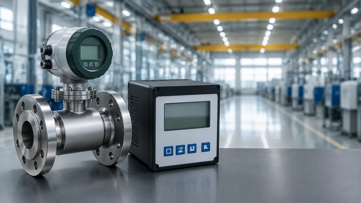
A complete flow meter and controller system consists of three primary layers: the sensing element, the signal processing unit (the controller), and the final control element.
The Sensing Element (Primary Meter)
In the context of Welk’s industrial solutions, the sensing element is often a high-precision level transmitter. For closed-pipe systems, hydrostatic pressure transmitters can also be used to calculate flow based on differential pressure across an orifice plate or Venturi tube, though non-contact level sensors remain the standard for open-channel and tank-emptying calculations.
The Controller (Secondary Instrument)
The controller acts as the "brain" of the system. It performs several critical functions:
* Signal Linearization: It converts the non-linear relationship between level and flow into a linear output.
* Totalization: It tracks the cumulative volume of liquid that has passed through the system over time.
* Data Logging: It records flow fluctuations for regulatory compliance and process analysis.
* Control Logic (PID): Many controllers include Proportional-Integral-Derivative (PID) functionality. If the flow rate deviates from a user-defined setpoint, the controller sends a signal to a valve or pump to adjust the flow accordingly.
Final Control Elements
To complete the loop, the controller interfaces with hardware such as:
* Variable Frequency Drives (VFDs): To adjust pump speeds.
* Modulating Valves: To restrict or increase flow in a pipeline.
* Dosing Pumps: In chemical applications, the controller may trigger a dosing pump to inject additives proportional to the measured flow rate.
Technical Selection Criteria
When specifying a flow meter and controller, engineers must evaluate the specific constraints of the application site. Failure to account for environmental variables can lead to measurement errors exceeding 20%.
Media Characteristics
The nature of the fluid is the first consideration. Is the liquid corrosive, prone to foaming, or laden with solids? For corrosive chemicals, non-contact radar or ultrasonic sensors are preferred to avoid material degradation. If the liquid surface is prone to heavy foam, radar (specifically 80GHz) is generally superior to ultrasonic, as sound waves are often absorbed by foam, leading to signal loss.
Accuracy Requirements
Standard open channel flow systems typically achieve accuracies between 2% and 5% of the full scale. If higher precision is required, the primary device (flume/weir) must be manufactured to extremely tight tolerances, and the level sensor must have a high resolution (e.g., ±1 mm or better).
Communication Protocols
Modern industrial automation relies on seamless data integration. Controllers should support standard protocols such as:
* 4-20mA HART: For analog signal transmission with superimposed digital data.
* Modbus RS485: For digital communication with PLCs and SCADA systems.
* Profibus/Profinet: For high-speed industrial networking.
Selection Table: Level-Based Flow Technologies
| Technology | Best Application | Advantages | Limitations |
| :— | :— | :— | :— |
| Ultrasonic | Water/Wastewater, Open Channels | Low cost, easy installation, no moving parts. | Sensitive to temperature changes and foam. |
| Radar (80GHz) | Chemical tanks, volatile liquids, outdoor flumes | High precision, unaffected by vapor or wind. | Higher initial investment. |
| Hydrostatic | Vented tanks, constant density liquids | Reliable in deep wells or pressurized vessels. | Requires contact with media; density dependent. |
| Magnetic Gauge | Visual flow/level confirmation in bypass | Highly visible, no power required for local display. | Limited to clean, conductive liquids. |
Installation Best Practices
Proper installation is the most significant factor in the long-term reliability of a flow meter and controller system.
Sensor Positioning
For open channel flow, the level sensor must be installed at a specific distance upstream from the weir or flume throat—usually 3 to 4 times the maximum head height. This ensures the measurement is taken in a zone where the liquid surface is stable and not affected by the "draw-down" effect caused by the acceleration of the fluid through the restriction.
Dead Band Considerations
All ultrasonic and radar sensors have a "dead band" or "blocking distance" directly beneath the sensor face where measurements cannot be taken. The sensor must be mounted high enough so that even at the maximum possible flow (maximum head), the liquid surface does not enter this dead band.
Stilling Wells
In applications where the liquid surface is turbulent or prone to waves, a stilling well (a vertical pipe submerged in the liquid) can be used to provide a calm surface for the sensor to measure. This is particularly useful for hydrostatic and ultrasonic sensors in large tanks or fast-moving channels.
Limitations and Operational Challenges
While robust, flow and level control systems face several common challenges:
* Sedimentation: In wastewater applications, solids can build up behind a weir, changing the channel's geometry and invalidating the flow calculation. Regular cleaning is required.
* Ambient Interference: For ultrasonic sensors, direct sunlight can heat the sensor body, leading to incorrect temperature compensation. Sunshields are recommended for outdoor installations.
* Vapor and Condensation: In chemical tanks, condensation on the sensor face can attenuate the signal. Many modern radar sensors feature drip-off antenna designs to mitigate this issue.
Maintenance and Calibration
To maintain accuracy, the flow meter and controller system should undergo periodic calibration. This involves:
1. Zero-Point Calibration: Verifying the sensor reading when there is zero flow (head = 0).
2. Span Verification: Using a manual measurement (e.g., a dip tape or ruler) to verify the sensor's accuracy at a known head height.
3. Controller Update: Ensuring the flow curve programmed into the controller matches the actual dimensions of the installed flume or weir.
For engineers looking to integrate these technologies into their facilities, it is essential to consult with a professional manufacturer who can provide customized solutions tailored to specific media and environmental conditions. You can Main Page to review product options and application support for your specific industrial needs.
Frequently Asked Questions (FAQ)
Q: Can I use an ultrasonic level sensor for flow measurement in a closed pipe?
A: Generally, no. Ultrasonic level sensors are designed for air-to-liquid surface measurement. For closed pipes, you would typically use a transit-time ultrasonic flow meter or a magnetic flow meter.
Q: How does a controller handle different flume shapes?
A: Most modern flow controllers come pre-programmed with standard formulas for common flumes (Parshall, Palmer-Bowlus) and weirs (V-notch, Rectangular). The user simply selects the type and enters the dimensions.
Q: What is the benefit of a dedicated controller over a PLC?
A: While a PLC can perform flow calculations, a dedicated flow controller often provides a more user-friendly interface for local operators, built-in totalizers that are protected against power loss, and specialized hardware for high-accuracy signal processing.
Q: Is radar always better than ultrasonic for flow?
A: Radar is technically superior in terms of accuracy and environmental resistance, but ultrasonic remains a highly effective and budget-friendly solution for standard water and wastewater applications where extreme conditions are not present.
By understanding these principles and selecting the right combination of sensing and control technology, industrial operators can ensure precise, reliable, and efficient flow management across their processes.