Insertion Flow Meter
Insertion Flow Meter
In industrial process control, measuring the flow of liquids and gases in large-diameter piping presents unique economic and logistical challenges. While inline flow meters provide high accuracy, their cost and installation complexity increase exponentially with pipe size. The insertion flow meter offers a versatile and cost-effective alternative by measuring the velocity of the fluid at a specific point within the cross-section of the pipe and using that data to calculate the total volumetric or mass flow rate.
As a specialized manufacturer of industrial measurement instruments, Welk provides high-precision solutions designed for demanding environments. This guide explores the technical principles, selection criteria, and installation requirements for insertion flow meters, serving as a practical reference for engineering teams and plant managers.
Understanding the Measurement Principles of Insertion Flow Meters
Before selecting an instrument, it is essential to understand how different technologies translate fluid movement into a measurable signal. Insertion meters do not measure the entire flow stream; instead, they sample the velocity at a representative point, typically at the center of the pipe or at a depth of one-eighth of the diameter, depending on the flow profile.
Thermal Dispersion Principle
Thermal dispersion insertion meters are primarily used for gas flow measurement. The sensor probe consists of two RTDs (Resistance Temperature Detectors). One RTD acts as a reference, measuring the ambient temperature of the gas, while the second RTD is heated to a constant differential temperature above the reference. As gas flows past the heated sensor, it carries away heat. The instrument measures the electrical power required to maintain the temperature differential, which is directly proportional to the mass flow rate of the gas. This method is highly sensitive to low flow rates and does not require external pressure or temperature compensation.
Electromagnetic Principle (Magmeters)
For conductive liquids, the electromagnetic insertion meter operates on Faraday’s Law of Induction. The probe generates a magnetic field at its tip. As a conductive liquid flows through this field, it generates a voltage proportional to its velocity. This voltage is picked up by electrodes on the probe surface. Because there are no moving parts, these meters are ideal for wastewater and slurry applications where mechanical wear is a concern.
Turbine Principle
An insertion turbine meter features a small rotor mounted at the end of the probe. The kinetic energy of the flowing fluid causes the rotor to spin at a speed proportional to the fluid velocity. A magnetic pickup or hall-effect sensor detects the passage of the turbine blades and generates a frequency signal. These meters are valued for their high dynamic range and repeatability in clean liquids and gases.
Vortex Shedding Principle
Insertion vortex meters utilize a bluff body (an obstruction) at the probe tip. As fluid flows past the bluff body, vortices are shed alternately from each side. The frequency of this vortex shedding is directly proportional to the fluid velocity over a wide range of Reynolds numbers. This technology is robust and suitable for high-temperature steam and gas applications.
Key Evaluation Criteria for Industrial Applications
Selecting the right insertion flow meter requires a thorough analysis of the process conditions. Unlike level measurement, where the focus is on the surface interface (as detailed on our Main Page), flow measurement requires an understanding of fluid dynamics and pipe geometry.
1. Fluid Characteristics: Determine if the fluid is a gas, liquid, or steam. For liquids, conductivity is critical for electromagnetic meters, while for gases, thermal conductivity and density affect thermal dispersion sensors.
2. Pipe Diameter: Insertion meters are most advantageous in pipes larger than 150 mm (6 inches). In smaller pipes, the probe itself may obstruct the flow, leading to significant pressure drop and measurement error.
3. Flow Profile and Reynolds Number: For an insertion meter to be accurate, the flow must be fully developed and predictable. This usually requires a specific Reynolds number (typically >10,000 for turbulent flow) to ensure the velocity at the measurement point accurately represents the average velocity.
4. Turndown Ratio: This is the ratio between the maximum and minimum flow rates the meter can accurately measure. Thermal meters offer high turndown (up to 100:1), while vortex and turbine meters are usually limited to 10:1 or 20:1.
Comparative Selection Table for Insertion Technologies
| Technology | Primary Media | Accuracy (Typical) | Turndown | Key Advantage |
| :— | :— | :— | :— | :— |
| Thermal Dispersion | Gases, Air | ±1% of Reading | 100:1 | No pressure/temp compensation needed |
| Electromagnetic | Conductive Liquids | ±2% of Velocity | 20:1 | No moving parts; handles solids |
| Turbine | Clean Liquids/Gases | ±1% of Velocity | 10:1 | Fast response; high repeatability |
| Vortex | Steam, Gas, Liquid | ±1.5% of Velocity | 15:1 | Robust; high temperature capability |
Critical Installation Guidelines for Accuracy
The most common cause of inaccuracy in insertion flow meters is improper installation. Because the meter only samples a small portion of the flow, the pipe's internal conditions must be controlled.
Straight Run Requirements
To achieve a stable flow profile, insertion meters require a minimum length of straight pipe upstream and downstream of the installation point.
- Upstream: Generally 20 to 30 pipe diameters (D) of straight run are required after elbows, valves, or pumps.
- Downstream: Usually 5 to 10 diameters (D) are required.
If these distances are not available, flow conditioners (vane or perforated plate types) must be installed to eliminate swirl and turbulence.
Insertion Depth and Orientation
For most applications, the sensor should be placed at the point of average velocity. In turbulent flow, this is often at the center of the pipe or at 1/8th of the diameter.
- Horizontal Pipes: For liquid flow, the probe should be installed from the side (3 o'clock or 9 o'clock position) to avoid air bubbles at the top and sediment at the bottom. For gas flow, top mounting is preferred to prevent moisture accumulation on the sensor.
- Vertical Pipes: Flow should ideally be moving upward to ensure the pipe is full and to minimize the impact of buoyancy on gas bubbles in liquids.
Hot Tapping Capabilities
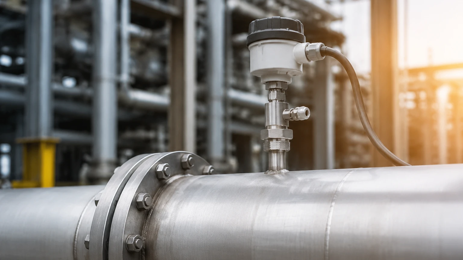
One of the primary benefits of the insertion flow meter is the ability to install it without shutting down the process. Using a "hot tap" kit, a ball valve is welded to the pipe, a hole is drilled through the valve while it is closed, and the probe is then inserted through the valve into the stream. This is a critical consideration for 24/7 industrial operations where downtime costs are prohibitive.
Common Risks and Operational Limitations
While versatile, insertion meters are not universal solutions. Engineers must be aware of the following limitations:
* Flow Profile Sensitivity: If the velocity profile is distorted by a nearby obstruction, the point measurement will not represent the true volume. This results in significant "profile factor" errors.
* Probe Fouling: In dirty fluids, debris can wrap around turbine rotors or coat the electrodes of electromagnetic probes. Thermal sensors are also sensitive to buildup, which acts as an insulator and slows response times.
* Mechanical Stress: In high-velocity applications, the probe is subject to significant drag forces and vibration. It is vital to verify the structural integrity of the probe (Wake Frequency Calculation) to prevent mechanical failure.
* Calibration Complexity: Unlike inline meters that can be calibrated in a flow lab using the actual pipe section, insertion meters are often calibrated in a wind tunnel or water loop and rely on mathematical models to adjust for the specific pipe size in the field.
Project Checklist: Information to Confirm Before Selection
To ensure the successful implementation of an insertion flow meter, the following data points should be confirmed with the manufacturer:
1. Fluid Properties: Exact composition, viscosity, density, and conductivity.
2. Operating Ranges: Minimum, normal, and maximum flow rates, as well as operating pressure and temperature.
3. Pipe Specifications: Material, Schedule (wall thickness), and exact Internal Diameter (ID).
4. Installation Site: Available straight run lengths and orientation (horizontal/vertical).
5. Output Requirements: 4-20mA, Pulse, Modbus RTU, or HART protocol for integration with PLC/SCADA systems.
6. Safety Certifications: Requirement for ATEX/IECEx (explosion-proof) or IP67/68 (waterproofing) ratings.
For more detailed technical support and to view our full range of measurement instrumentation, please visit our Main Page.
Frequently Asked Questions (FAQ)
1. Can an insertion flow meter measure bi-directional flow?
Some technologies, such as electromagnetic and certain thermal dispersion designs, can measure flow in both directions. However, turbine and vortex meters are typically unidirectional. If bi-directional measurement is required, this must be specified during the selection phase.
2. How often do insertion meters need calibration?
Calibration frequency depends on the fluid and the technology. For clean gas applications using thermal dispersion, a check every 2-3 years is common. For turbine meters in abrasive fluids, annual inspection of the rotor is recommended. Many modern digital meters offer self-diagnostic features that alert operators when the sensor performance deviates from factory benchmarks.
3. What is the maximum pipe size for an insertion meter?
There is theoretically no upper limit to the pipe size, as long as the probe is long enough to reach the required insertion depth. They are commonly used in ducts and pipes exceeding 2000 mm (80 inches) in diameter, where inline meters would be cost-prohibitive.
4. Is a pressure drop significant with these meters?
No. Because the probe occupies a very small percentage of the pipe's cross-sectional area, the permanent pressure loss is negligible compared to orifice plates or venturi tubes. This makes insertion meters an energy-efficient choice for large-scale distribution systems.
5. Can I use an insertion meter for steam?
Yes, insertion vortex meters are specifically designed for saturated and superheated steam. They are built with robust materials to withstand the high temperatures and pressures associated with steam headers and distribution lines.
By carefully considering the measurement principle and adhering to strict installation standards, the insertion flow meter provides a reliable, high-performance solution for modern industrial fluid management. Whether monitoring compressed air, cooling water, or industrial effluent, these instruments deliver the data necessary for process optimization and energy conservation.