Differential Pressure Transmitter Calibration
Differential Pressure Transmitter Calibration
In industrial process control, the accuracy of level, flow, and pressure measurements is fundamental to operational safety and efficiency. Differential pressure (DP) transmitters are among the most versatile instruments in a plant, used extensively for measuring liquid levels in pressurized tanks, flow rates across orifice plates, and pressure drops across filters. However, the reliability of these measurements depends entirely on precise differential pressure transmitter calibration.
As a professional manufacturer of industrial level measurement instruments, Welk emphasizes that calibration is not merely a maintenance task but a critical engineering procedure. This guide explores the principles of differential pressure measurement, the technical steps for calibration, and the practical considerations necessary to maintain instrument integrity in demanding environments.
Measurement Principles of Differential Pressure Transmitters
Before performing a calibration, it is essential to understand how a DP transmitter functions. The core of the instrument is a sensing element, typically a metallic or ceramic diaphragm, situated between two pressure chambers: the High-Pressure (H) side and the Low-Pressure (L) side.
The Differential Equation
The transmitter measures the difference in force exerted on these two sides. The mathematical relationship is expressed as:
$$\Delta P = P_{High} – P_{Low}$$
In a liquid level application for a closed tank, the high-pressure side is connected to the bottom of the vessel, while the low-pressure side is connected to the top (the headspace). This configuration allows the instrument to subtract the internal tank pressure from the total pressure measured at the bottom, leaving only the hydrostatic head pressure exerted by the liquid.
Signal Conversion
The mechanical displacement of the diaphragm is converted into an electrical signal—most commonly a 4-20mA analog output or a digital HART signal. Calibration ensures that the Lower Range Value (LRV), representing 0% of the measured variable, and the Upper Range Value (URV), representing 100%, correspond exactly to 4mA and 20mA, respectively.
The Importance of Regular Calibration
Differential pressure transmitter calibration is required to counteract "drift," which is the gradual deviation of the sensor’s output over time. Factors contributing to drift include:
* Mechanical Fatigue: Repeated cycling of the sensing diaphragm.
* Temperature Fluctuations: Thermal expansion and contraction of internal components and fill fluids.
* Static Pressure Effects: High line pressures can cause small but significant shifts in the zero point.
* Overpressure Events: Sudden pressure spikes that may slightly deform the diaphragm.
Regular calibration cycles ensure that the instrument remains within its specified accuracy class (e.g., ±0.075% or ±0.1% of span). For those looking to integrate high-precision instruments into their systems, they can consult the Main Page to review product options and application support.
Calibration Equipment and Setup
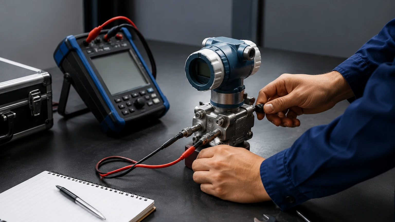
To perform an accurate calibration, a controlled environment or a stable field setup is required. The following equipment is standard for a professional calibration bench:
1. Pressure Source: A pneumatic or hydraulic hand pump capable of generating the required range.
2. Digital Pressure Gauge (Master Gauge): A high-accuracy reference standard, typically four times more accurate than the transmitter under test.
3. Multimeter or Process Calibrator: To measure the 4-20mA output loop.
4. HART Communicator: For digital adjustment of smart transmitters.
5. Power Supply: A stable 24V DC source.
6. Manifold: A three-way or five-way valve manifold to isolate the transmitter from the process and equalize pressure.
Step-by-Step Differential Pressure Transmitter Calibration Procedure
A standard calibration involves a five-point check (0%, 25%, 50%, 75%, and 100% of the span) in both increasing and decreasing directions to check for hysteresis.
Step 1: Preparation and Isolation
Isolate the transmitter from the process using the manifold. Open the equalizing valve to ensure both the High and Low sides are at the same pressure. Vent the chambers to the atmosphere if the calibration is performed relative to ambient pressure.
Step 2: Zero Trim
With both ports vented to the atmosphere (zero differential pressure), the output should be exactly 4.000mA. If there is a deviation, perform a "Zero Trim" using the HART communicator or the local zero adjustment button. This aligns the electronic 0% with the physical zero pressure.
Step 3: Applying Pressure (Span Check)
Connect the pressure source to the High-Pressure port while leaving the Low-Pressure port vented to the atmosphere. Gradually apply pressure equal to the Upper Range Value (URV). For example, if the calibrated range is 0 to 250 mbar (25 kPa), apply 250 mbar.
Step 4: Span Trim
Check the output at the URV. It should read 20.000mA. If the reading is outside the tolerance, perform a "Span Trim." It is important to note that adjusting the span may slightly affect the zero point, so re-verifying the zero is often necessary.
Step 5: Linearity and Hysteresis Check
Perform the full five-point test. Record the mA output at each interval:
* 0% (e.g., 0 mbar) -> 4mA
* 25% (e.g., 62.5 mbar) -> 8mA
* 50% (e.g., 125 mbar) -> 12mA
* 75% (e.g., 187.5 mbar) -> 16mA
* 100% (e.g., 250 mbar) -> 20mA
Repeat the steps in descending order (100% to 0%) to identify any hysteresis (lag in the diaphragm's return to its original shape).
Practical Selection and Application Table
Choosing the right DP transmitter is as important as the calibration itself. Different applications require specific diaphragm materials and pressure ranges.
| Application Type | Typical Pressure Range | Recommended Diaphragm Material | Calibration Frequency | Key Consideration |
| :— | :— | :— | :— | :— |
| Clean Water Level | 0–500 mbar | Stainless Steel 316L | Annual | Hydrostatic head accuracy |
| Chemical Storage | 0–1000 mbar | Hastelloy C / PTFE Coated | Bi-annual | Corrosion resistance |
| High-Pressure Steam | 0–2.5 bar | Monel / Tantalum | Quarterly | Static pressure shift |
| Oil & Gas Flow | 0–5 bar | Stainless Steel 316L | Bi-annual | Hysteresis and linearity |
Installation Considerations for Calibration Stability
The physical installation of a DP transmitter significantly impacts how often it requires calibration and how accurate those calibrations will be in the field.
Impulse Line Management
Impulse lines (the pipes connecting the process to the transmitter) must be sloped correctly to prevent gas bubbles from being trapped in liquid lines or liquid from condensing in gas lines. Trapped fluids create a false differential pressure, leading to "calibration errors" that are actually installation issues.
Mounting Position
Transmitters are often calibrated in a vertical position. If the unit is mounted horizontally in the field, the weight of the internal fill fluid against the diaphragm can cause a zero shift. Always perform a final zero trim *after* the unit is installed in its permanent orientation.
Temperature Effects
In outdoor installations, solar radiation can heat one side of the transmitter more than the other, causing a localized density change in the fill fluid. Using sunshades or heat tracing can help maintain calibration stability.
Limitations and Challenges
While differential pressure transmitter calibration is highly effective, certain limitations must be acknowledged:
* Turndown Ratio Limits: While modern transmitters allow for high turndown ratios (e.g., 100:1), calibrating a 10-bar sensor to measure only 0.1 bar will significantly increase the Total Probable Error (TPE).
* Non-Linear Fluids: In flow applications using orifice plates, the relationship between DP and flow is a square root function ($Flow \propto \sqrt{\Delta P}$). Calibration must account for whether the square root extraction is performed in the transmitter or the control system.
* Ambient Pressure Variations: In very low-range DP applications, changes in barometric pressure can influence readings if the low-pressure side is vented to the atmosphere.
Frequently Asked Questions (FAQs)
1. How often should I calibrate my DP transmitter?
For most industrial applications, an annual calibration is sufficient. However, in critical safety loops or high-vibration environments, quarterly or bi-annual checks are recommended. Always follow the manufacturer’s drift specifications.
2. What is the difference between a Zero Trim and a Re-ranging?
A Zero Trim corrects the sensor's offset at zero pressure without changing the scale. Re-ranging (or re-spanning) changes the pressure values that correspond to 4mA and 20mA. For example, changing a 0–100 mbar range to 0–150 mbar is re-ranging.
3. Can I calibrate a DP transmitter without a pressure pump?
If the transmitter is a "Smart" HART-enabled device, you can perform a "bench calibration" by digitally setting the LRV and URV. However, this only verifies the electronics. A true calibration requires an actual pressure source to verify the physical integrity of the diaphragm.
4. What is "Wet Leg" calibration?
In level measurement where the low-pressure impulse line is filled with a reference liquid (to prevent condensation), the weight of this liquid column must be subtracted from the measurement. This is handled during calibration by applying a "Zero Elevation" or "Zero Suppression" offset.
Conclusion
Effective differential pressure transmitter calibration is the cornerstone of reliable process instrumentation. By understanding the underlying physics of the diaphragm, utilizing high-precision reference standards, and accounting for environmental factors like static pressure and temperature, engineers can ensure their measurement loops remain accurate over the long term. Welk continues to provide robust measurement solutions designed for ease of maintenance and high stability. For further technical specifications and product selection, professionals are encouraged to visit the Main Page to explore our full range of industrial level and pressure instruments.
Download Differential Pressure Transmitter Calibration as a PDF