Prowirl R
Prowirl R
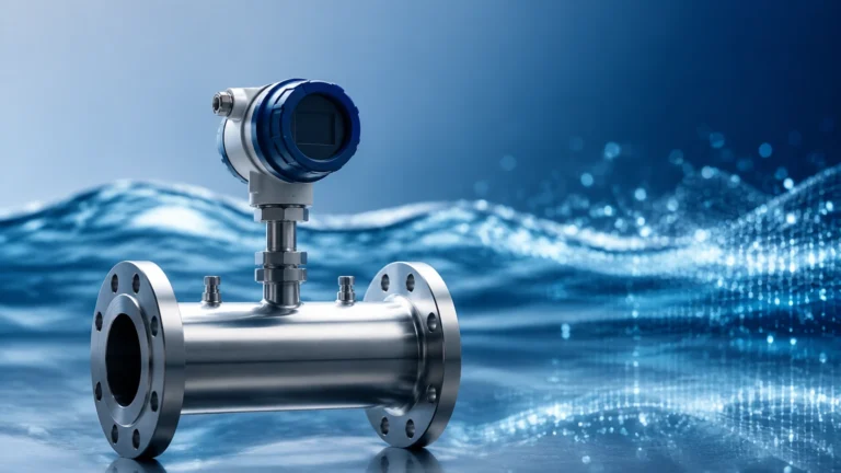
In the landscape of industrial process control, the accurate measurement of steam, gases, and liquids is fundamental to operational efficiency and safety. Among the various technologies available, vortex flowmeters have established themselves as a reliable standard. The Prowirl R represents a specific evolution of this technology, characterized by its integrated line size reduction. This design addresses a common engineering challenge: measuring fluids in piping systems where the flow velocity is too low for a standard full-bore meter to detect accurately.
By incorporating the reduction directly into the meter body, the Prowirl R eliminates the need for expensive field-installed reducers and expanders while ensuring the flow profile is optimized for the sensor. This article provides a technical overview of the Prowirl R, its operating principles, selection criteria, and its role alongside other process instruments such as those found on the Main Page of industrial measurement catalogs.
Measurement Principles of Vortex Flowmeters
The Prowirl R operates on the Karman Vortex Street principle. When a fluid flows past a bluff body (a non-streamlined object) placed in the center of the pipe, it creates alternating vortices on downstream sides. The frequency at which these vortices are shed is directly proportional to the velocity of the fluid.
The Physics of Vortex Shedding
The relationship is defined by the Strouhal Law:
f = St × (v / d)
Where:
* f is the vortex shedding frequency.
* St is the Strouhal number (a constant for a specific bluff body shape).
* v is the flow velocity.
* d is the width of the bluff body.
In a standard vortex meter, if the flow velocity is too low, the pressure pulses generated by the vortices are too weak for the sensor to detect. This is particularly common in steam applications where pipes are often oversized to minimize pressure drop during peak demand, resulting in low velocities during normal operation.
The "R" Advantage: Integrated Reduction
The "R" in Prowirl R stands for "Reduced." Unlike a standard meter (often designated as Prowirl F or full-bore), the Prowirl R features a narrowing of the internal diameter within the meter body itself. This reduction increases the fluid velocity at the point of measurement, allowing the meter to capture low flow rates that would otherwise fall below the "low-cut" threshold of a full-bore instrument.
There are typically two versions available:
1. R1: A one-step reduction (e.g., a DN 80 pipe connection with a DN 50 internal measuring tube).
2. R2: A two-step reduction (e.g., a DN 80 pipe connection with a DN 40 internal measuring tube).
Key Features and Advantages
The integration of the reduction into the meter body offers several technical and economic benefits for plant operators and design engineers.
1. Reduced Installation Costs
In traditional setups, if a pipe is 100 mm (DN 100) but the flow requires an 80 mm meter for accuracy, the contractor must purchase and install two reducers and additional piping. The Prowirl R comes with DN 100 flanges but has the internal geometry of a smaller meter, saving on hardware and labor costs.
2. Optimized Flow Profile
External reducers often introduce turbulence that requires long straight runs of pipe (often 20 to 40 times the pipe diameter) to settle before reaching the meter. Because the reduction in the Prowirl R is engineered and factory-calibrated, the flow profile is predictable, often allowing for shorter inlet runs than a field-assembled reduction setup.
3. Integrated Temperature and Pressure Compensation
Modern iterations of this meter often include built-in temperature sensors and the ability to interface with external pressure transmitters. This allows the device to calculate mass flow and energy (especially important for saturated steam) without requiring a separate flow computer.
4. Robustness and Stability
Using capacitive sensors (often referred to as DSC or Differential Swirl Compensation sensors), the meter can distinguish between the pressure pulses of vortices and external pipe vibrations. This makes the Prowirl R suitable for harsh industrial environments where heavy machinery or pumps might create mechanical noise.
Selection Criteria and Technical Specifications
Choosing between a full-bore meter and a Prowirl R requires a detailed analysis of the process conditions. The primary goal is to ensure the expected flow range falls within the meter's linear measurement range.
Sizing Table (Conceptual Example)
| Nominal Diameter (DN) | Internal Measuring Bore | Min. Flow (Water) | Max. Flow (Water) | Min. Flow (Steam) |
| :— | :— | :— | :— | :— |
| DN 50 (Full) | 50 mm | 3.2 m³/h | 95 m³/h | 45 kg/h |
| DN 50 (R1) | 40 mm | 2.1 m³/h | 60 m³/h | 28 kg/h |
| DN 80 (Full) | 80 mm | 7.5 m³/h | 220 m³/h | 110 kg/h |
| DN 80 (R1) | 50 mm | 3.2 m³/h | 95 m³/h | 45 kg/h |
| DN 80 (R2) | 40 mm | 2.1 m³/h | 60 m³/h | 28 kg/h |
*Note: Values are illustrative. Actual sizing should be performed using manufacturer-specific software taking into account density, viscosity, and Reynolds numbers.*
When to Choose Prowirl R
* Low Flow Rates: When the minimum required flow rate is below the measurable limit of a full-bore meter.
* Space Constraints: When there is insufficient space to install external pipe reducers and the necessary straight pipe runs.
* Steam Measurement: Particularly in heating systems where summer loads are significantly lower than winter loads.
* Standardization: When a facility wants to maintain a consistent outer pipe diameter for insulation and support purposes while varying the internal meter size based on specific loop requirements.
Installation Considerations
Proper installation is critical for the accuracy of any vortex meter. Despite the integrated reduction, certain rules must be followed to ensure a stable Karman Vortex Street.
Straight Pipe Requirements
To ensure a fully developed flow profile, the meter typically requires:
* Upstream: Minimum 20xDN (where DN is the inlet pipe diameter).
* Downstream: Minimum 5xDN.
If there are multiple bends or valves upstream, these requirements may increase. However, the Prowirl R is often more forgiving of upstream disturbances than a standard meter preceded by a field reducer.
Orientation and Mounting
* Liquid Flow: The pipe must always be full. Vertical upward flow is preferred to ensure any entrained air passes through without affecting the sensor.
* Steam/Gas Flow: The meter can be installed in horizontal or vertical pipes. In horizontal steam lines, the sensor should be mounted to the side (90 degrees) to prevent condensate from pooling around the bluff body or sensor head.
* Insulation: While the pipe should be insulated to save energy, the electronics housing and the support strut of the meter should remain exposed to ambient air to prevent overheating of the transmitter.
Limitations and Common Risks
While the Prowirl R is a versatile tool, it is not a universal solution for every flow application.
1. Pressure Drop: Because the meter reduces the pipe diameter, it inherently creates a higher pressure drop than a full-bore meter. In low-pressure gas systems, this must be calculated to ensure downstream pressure remains sufficient for the process.
2. Cavitation: In liquid applications, the increased velocity and subsequent pressure drop within the reduced bore can lead to cavitation. This occurs if the local pressure drops below the vapor pressure of the liquid. Cavitation will damage the meter and lead to massive measurement errors.
3. High Viscosity: Vortex meters are generally limited to fluids with a Reynolds number above 5,000 to 10,000. Highly viscous liquids (like heavy oils) do not shed vortices reliably.
4. Abrasive Media: The bluff body is a precision-engineered component. Fluids containing abrasive solids can wear down the edges of the bluff body, changing the Strouhal number and drifting the calibration over time.

Complementary Technologies in Process Automation
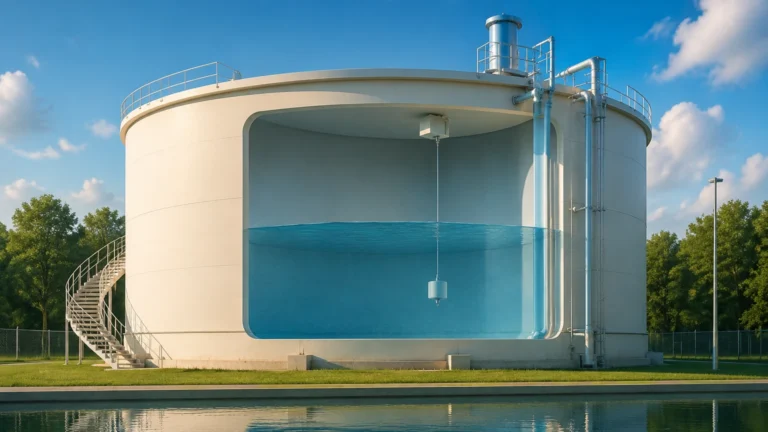
In a complex industrial facility, flow measurement is rarely an isolated requirement. It is usually part of a broader mass balance or inventory control strategy. For example, in a chemical storage tank system, an engineer might use a Prowirl R to measure the nitrogen blanketing gas flow or the steam used for tank heating jackets.
Simultaneously, the level within those tanks must be monitored using technologies like those provided by Welk, such as radar level meters or ultrasonic sensors. While the Prowirl R tracks the "energy" or "medium" entering the system, level instruments track the "inventory" remaining. For a comprehensive look at level measurement solutions that work in tandem with flow systems, engineers often consult the Main Page of specialized instrumentation providers to ensure compatibility in communication protocols (such as HART, Modbus, or Foundation Fieldbus).
Maintenance and Troubleshooting
Vortex meters are known for being "maintenance-free" because they have no moving parts. However, periodic checks are necessary to ensure long-term reliability.
* Visual Inspection: Check for signs of leakage at the flanges and inspect the electronics housing for moisture ingress.
* Zero-Point Check: Unlike magnetic flowmeters, vortex meters do not have a drifting zero. If the meter shows flow when the valves are closed, it is likely detecting pipe vibration or electrical interference.
* Sensor Cleaning: In steam systems with poor water treatment, scale can build up on the bluff body. This changes the geometry and the shedding frequency. Periodic cleaning or inspection during plant shutdowns is recommended.
Frequently Asked Questions (FAQs)
Q: Can the Prowirl R measure bidirectional flow?
A: No. Vortex meters are inherently unidirectional. The bluff body and sensor are designed to detect vortices shed in one specific direction. Installing the meter backward will result in no reading or significant errors.
Q: What is the difference between R1 and R2?
A: R1 signifies a one-step reduction (e.g., 3" to 2"), while R2 signifies a two-step reduction (e.g., 3" to 1.5"). R2 allows for the measurement of even lower flow rates but introduces a higher pressure drop.
Q: Is the Prowirl R suitable for hygienic applications?
A: While vortex meters are used in some food and beverage utilities (like steam), the presence of the bluff body in the flow stream means they are generally not considered "hygienic" or "CIP/SIP" friendly for direct contact with food products compared to electromagnetic or Coriolis meters.
Q: How does wet steam affect the Prowirl R?
A: Wet steam can lead to measurement inaccuracies because the meter is calibrated for single-phase flow. However, many modern Prowirl units include "Wet Steam Detection" functions that can alert operators when the steam quality drops below a certain percentage (e.g., 80%), preventing errors in energy billing.
Conclusion
The Prowirl R is a specialized engineering solution that simplifies the measurement of low-velocity flows in industrial piping. By integrating the reduction into the meter body, it reduces installation complexity, lowers costs, and ensures a predictable flow profile for the Karman Vortex sensor. When integrated into a complete process control system—alongside reliable level measurement instruments and pressure transmitters—it provides the data necessary for optimized energy management and process safety. For those designing new systems or retrofitting existing ones, understanding the balance between flow range, pressure drop, and installation constraints is key to selecting the right version of this robust technology.