Industrial Clamp on Flow Meter
Industrial Clamp on Flow Meter
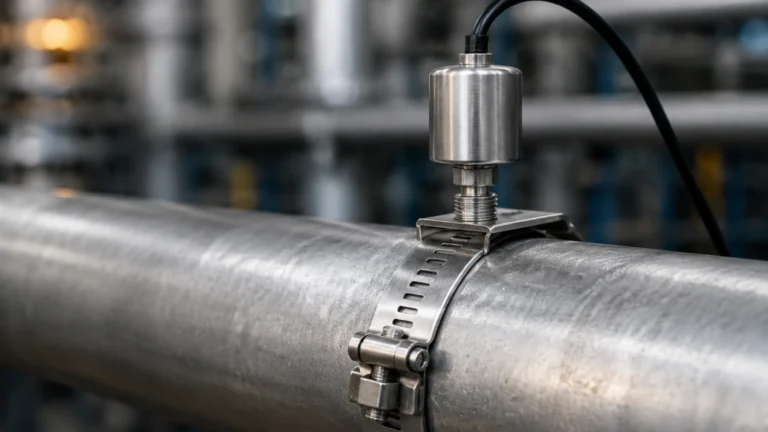
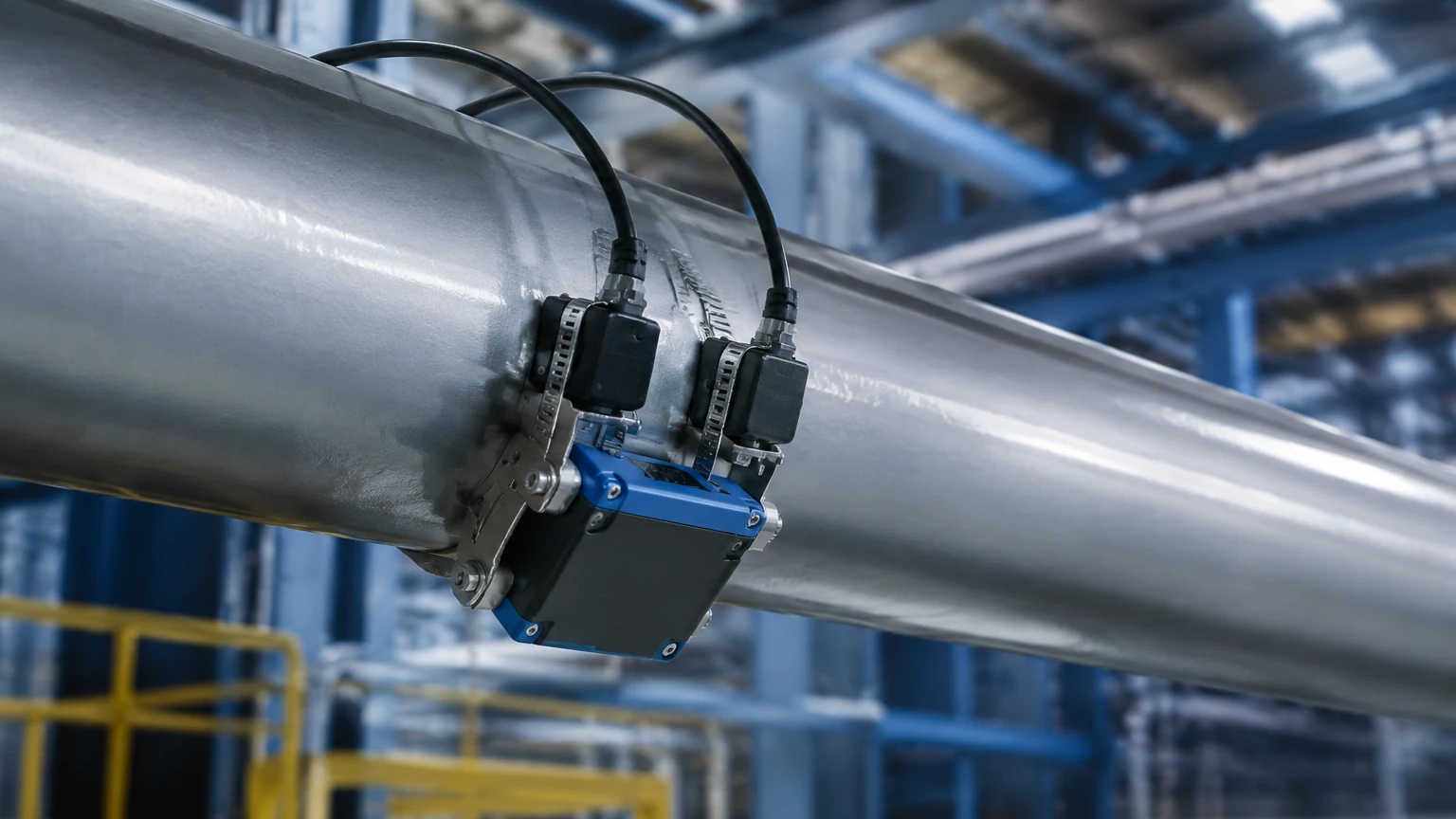
In the landscape of modern industrial process control, the ability to measure fluid dynamics without interrupting production or compromising the integrity of piping systems is a critical advantage. The industrial clamp on flow meter, primarily utilizing ultrasonic technology, has emerged as a cornerstone for non-invasive liquid measurement. Unlike traditional inline meters that require pipe cutting and flange mounting, these devices attach to the exterior of the pipe, offering a versatile and cost-effective solution for a variety of sectors, including water treatment, chemical processing, and oil and gas.
For engineers and facility managers, understanding the underlying principles, selection criteria, and installation nuances of these instruments is essential for ensuring long-term accuracy and operational efficiency. While flow measurement is a distinct discipline, it often works in tandem with level measurement systems to provide a complete picture of mass balance and inventory management. For those seeking comprehensive industrial measurement solutions, reviewing the Main Page of specialized manufacturers provides a broader perspective on how these technologies integrate into automated systems.
Measurement Principles: How Clamp-on Technology Works
Industrial clamp-on flow meters operate using ultrasonic waves to determine the velocity of a liquid within a closed pipe. There are two primary methods used in industrial applications: Transit-Time and Doppler Effect. Selecting the correct principle is the first step in ensuring application success.
Transit-Time Ultrasonic Flow Meters
Transit-time technology is the most common method for clean liquids. It relies on the principle that ultrasonic signals traveling in the direction of flow move faster than signals traveling against it. Two transducers are mounted on the pipe, acting as both transmitters and receivers. They alternate sending pulses of high-frequency sound across the pipe at an angle.
If $t_{up}$ is the time taken for the signal to travel upstream and $t_{down}$ is the time taken to travel downstream, the difference in time ($Δt$) is directly proportional to the velocity of the fluid ($v$). The formula generally follows:
$$v = K · Δt / (t_{up} · t_{down})$$
Where $K$ is a constant based on the pipe geometry and the speed of sound in the liquid. Because this method requires the signal to pass clearly through the fluid, it is best suited for liquids with less than 2% total suspended solids (TSS) or aeration.
Doppler Effect Flow Meters
Doppler flow meters are designed for "dirty" liquids, such as wastewater, slurries, or aerated fluids. This method requires particles or bubbles (discontinuities) in the fluid to reflect the ultrasonic signal. The meter transmits a signal of a known frequency; when this signal hits a moving particle, it reflects back to the receiver with a frequency shift. The magnitude of this shift is proportional to the flow velocity. While generally less accurate than transit-time meters, Doppler meters are indispensable in applications where the fluid is too opaque for transit-time signals.
Key Evaluation Criteria for Selection
When specifying an industrial clamp on flow meter, several technical parameters must be evaluated to ensure compatibility with the existing infrastructure.
Pipe Material and Condition
Ultrasonic signals must pass through the pipe wall, the liquid, and back through the wall. Therefore, the pipe material significantly impacts signal attenuation. Standard materials like carbon steel, stainless steel, PVC, and copper are excellent conductors. However, pipes with internal liners (e.g., cement, rubber, or bitumen) present challenges because the interface between the pipe and the liner can create an air gap that reflects the signal before it enters the fluid.
Fluid Properties
The viscosity and temperature of the fluid affect the speed of sound and the Reynolds number, which determines whether the flow is laminar or turbulent. Most industrial clamp-on meters include built-in compensation for temperature and viscosity, but extreme temperatures (above 150°C / 302°F) require specialized high-temperature transducers and mounting tracks.
Accuracy and Rangeability
Typical accuracy for a well-installed industrial clamp-on meter ranges from ±0.5% to ±2% of the flow rate. They offer high turndown ratios (rangeability), often exceeding 100:1, allowing for precise measurement at both very low and very high velocities (typically 0.1 m/s to 12 m/s or 0.3 ft/s to 40 ft/s).
Practical Selection Table
The following table provides a quick reference for choosing between transit-time and Doppler technologies based on application characteristics.
| Feature | Transit-Time (Clean Liquid) | Doppler (Dirty Liquid) |
| :— | :— | :— |
| Fluid Type | Potable water, oils, chemicals | Sewage, slurries, aerated liquids |
| Suspended Solids | < 2% by volume | > 100 ppm (typically > 0.1 mm size) |
| Typical Accuracy | ±0.5% to ±1% | ±2% to ±5% |
| Pipe Size Range | 15 mm to 6000 mm | 25 mm to 6000 mm |
| Installation | Non-invasive clamp-on | Non-invasive clamp-on |
| Maintenance | Very low | Very low |
Installation Considerations and Best Practices
The performance of an industrial clamp on flow meter is heavily dependent on the quality of the installation. Unlike electromagnetic meters, which are relatively forgiving, ultrasonic meters require precise transducer placement.
Straight Pipe Requirements
To ensure a fully developed and stable flow profile, the meter should be installed on a straight section of pipe. The general rule of thumb is "10D Upstream and 5D Downstream," meaning there should be a straight run of 10 times the pipe diameter before the meter and 5 times the diameter after it. Obstructions like valves, elbows, or pumps create turbulence that can result in erratic readings.
Transducer Mounting Methods
There are three common mounting configurations:
1. V-Method: Used for pipe diameters from 25 mm to 400 mm (1" to 16"). The signal crosses the pipe twice. This is the standard method for most industrial applications.
2. Z-Method: Used for large pipes (above 400 mm / 16") or where the liquid is slightly attenuating. The transducers are placed on opposite sides of the pipe, and the signal crosses only once.
3. W-Method: Used for very small pipes (below 50 mm / 2"). The signal bounces multiple times, increasing the path length to improve resolution in low-flow scenarios.
Surface Preparation and Couplant
The pipe surface must be cleaned of rust, loose paint, and scale. A smooth, flat surface is required for the transducer to make full contact. An ultrasonic couplant (grease or gel) is applied between the transducer face and the pipe to eliminate air gaps. In permanent installations, solid couplant pads or high-temperature silicone are often used to prevent the couplant from drying out over time.
Limitations and Common Risks
While highly versatile, clamp-on flow meters are not a universal solution for every process. Engineers should be aware of the following limitations:
* Aeration and Bubbles: In transit-time meters, excessive air bubbles will scatter the ultrasonic beam, leading to a "signal loss" error. This is common in suction lines or pipes where the liquid drops into a tank.
* Pipe Wall Scaling: Internal scaling (calcium buildup) acts as an insulator and can significantly degrade the signal. In some cases, the meter may need to be oversized or moved to a newer section of the piping network.
* Wall Thickness Uncertainty: The meter calculates flow based on the internal diameter. If the actual pipe wall thickness differs from the programmed value (due to corrosion or manufacturing tolerances), the resulting flow calculation will be inaccurate. Using a thickness gauge to verify the pipe wall before installation is a recommended best practice.
Integration with Industrial Systems
Modern industrial clamp on flow meters are designed for seamless integration into SCADA and PLC systems. They typically offer multiple output options, including 4-20mA analog signals, pulse outputs for totalization, and digital protocols such as Modbus RS485, HART, or Profibus.
In many industrial automation setups, flow data is combined with level data from radar or ultrasonic level sensors to calculate the efficiency of pumps or to detect leaks in large storage systems. By comparing the flow rate into a tank with the rate of level change, operators can identify discrepancies that might indicate structural failures or sensor drift. For a deeper look at the instruments that complement flow measurement, such as radar and hydrostatic sensors, visit the Main Page for technical specifications and application guides.
Frequently Asked Questions (FAQ)
Q: Can a clamp-on flow meter measure gas?
A: While most industrial clamp-on meters are designed for liquids, specialized high-frequency ultrasonic meters exist for high-pressure gas applications. However, standard liquid meters will not work on gas lines due to the low density of gas and the high signal attenuation.
Q: How often does the ultrasonic couplant need to be reapplied?
A: For temporary surveys, standard gel lasts a few days. For permanent installations, using a high-quality silicone grease or a solid epoxy couplant can ensure the signal remains stable for years without maintenance.
Q: Does the pipe need to be full for accurate measurement?
A: Yes, for standard clamp-on meters, the pipe must be completely full. If the pipe is partially full, the meter will either provide an error or a highly inaccurate reading. For partially filled pipes, specialized area-velocity flow meters are required.
Q: How does pipe vibration affect the meter?
A: Minor industrial vibrations generally do not affect ultrasonic signals, as the frequencies used by the transducers (typically 0.5 MHz to 2 MHz) are much higher than mechanical vibration frequencies. However, extreme vibration can loosen the mounting clamps, so secure fastening is essential.
Conclusion
The industrial clamp on flow meter represents a significant advancement in process instrumentation, providing a non-intrusive, flexible, and accurate means of monitoring fluid flow. By understanding the physics of transit-time and Doppler measurement, and by adhering to strict installation protocols regarding pipe preparation and straight runs, industrial operators can achieve reliable data without the downtime associated with traditional meter installation. As part of a holistic approach to industrial automation, these meters work alongside level and pressure sensors to ensure optimal process performance and resource management.