Electromagnetic Flowmeters
Electromagnetic Flowmeters
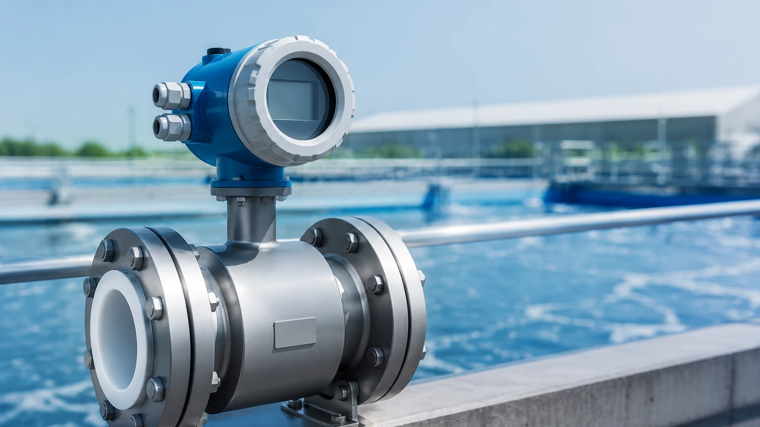
Electromagnetic flowmeters, commonly referred to as magmeters, are among the most versatile and accurate instruments for measuring the volumetric flow rate of electrically conductive liquids. In industrial environments ranging from municipal water treatment to complex chemical processing, these meters provide a profile of reliability due to their lack of moving parts and minimal pressure drop. This guide explores the technical foundations, selection criteria, and installation requirements for electromagnetic flowmeters, providing engineering professionals with the data needed to integrate these devices into broader process automation systems.
Fundamental Principles of Electromagnetic Flow Measurement
Before selecting a flowmeter, it is essential to understand the physics governing its operation. Electromagnetic flowmeters operate based on Faraday’s Law of Electromagnetic Induction. This law states that a voltage is induced when a conductive medium moves through a magnetic field.
In a magmeter, the sensor consists of a non-magnetic tube lined with an insulating material. Two magnetic coils are positioned outside or within the flow tube to generate a constant magnetic field ($B$) across the cross-section of the pipe. As a conductive liquid flows through this field with a certain velocity ($v$), it acts as a moving conductor. This movement induces an electromotive force (voltage, $E$) that is picked up by two electrodes mounted on opposite sides of the tube.
The relationship is expressed by the formula:
$$E = k \cdot B \cdot D \cdot v$$
Where:
* E: Induced voltage
* k: Instrument constant
* B: Magnetic field strength
* D: Inner diameter of the pipe (distance between electrodes)
* v: Average velocity of the liquid
Because the magnetic field strength and the pipe diameter are fixed, the induced voltage is directly proportional to the average flow velocity. The transmitter then converts this microvolt signal into a standard industrial output, such as 4-20mA, pulse, or a digital protocol like Modbus or HART. This linear relationship allows for high accuracy across a wide turndown ratio.
Key Components and Construction
The durability and performance of electromagnetic flowmeters depend heavily on their construction materials. A standard unit comprises two main parts: the sensor (the part in contact with the process) and the transmitter (the electronics that process the signal).
The Flow Tube and Liner
Since the flow tube is usually made of stainless steel (a conductor), it must be lined with an insulating material to prevent the induced voltage from shorting out against the pipe wall. The choice of liner is the most critical factor in determining the meter’s compatibility with the process fluid.
Electrodes
Electrodes are the "sensing" elements that detect the induced voltage. They must be resistant to corrosion and fouling. Common materials include Stainless Steel 316L, Hastelloy C, Titanium, and Tantalum. In applications involving slurries or fluids that tend to coat surfaces, specialized "bullet-shaped" or self-cleaning electrodes may be utilized.
Selection Criteria: Liners and Electrodes
Choosing the correct material combination is vital for ensuring a long service life and preventing measurement drift. The following table provides a practical reference for common industrial applications.
| Liner Material | Temperature Range | Characteristics | Typical Applications |
| :— | :— | :— | :— |
| Neoprene / Hard Rubber | -10°C to +80°C | Good abrasion resistance; economical. | Municipal water, wastewater, cooling water. |
| Polyurethane | -10°C to +60°C | Excellent abrasion resistance for solids. | Mining slurries, sand-water mixtures. |
| PTFE (Teflon) | -20°C to +120°C | High chemical resistance; anti-adhesive. | Strong acids, bases, corrosive chemicals. |
| PFA | -20°C to +150°C | Similar to PTFE but better for vacuum and high temp. | High-temperature chemical processing, food & beverage. |
| Ceramic | -20°C to +180°C | Extreme hardness and heat resistance. | Highly abrasive and corrosive high-temp fluids. |
Electrode Material Selection
* 316L Stainless Steel: Standard for water and mildly corrosive liquids.
* Hastelloy C: Used for aggressive chemicals like seawater and organic acids.
* Titanium: Preferred for chloride-heavy environments and bleaching agents.
* Tantalum: Reserved for the most aggressive acids, such as hydrochloric or sulfuric acid.
* Platinum-Iridium: Used in highly specialized chemical applications where other metals fail.
Installation Requirements and Best Practices
To maintain the accuracy specified by the manufacturer—often ±0.5% or better—electromagnetic flowmeters must be installed according to specific hydraulic guidelines. The goal is to ensure a stable, symmetrical flow profile at the point of measurement.
Straight Pipe Runs
Flow disturbances caused by valves, pumps, or elbows can create turbulence that affects the magnetic field's interaction with the fluid. A general rule of thumb is the "5D/2D" rule: provide a straight pipe length of at least 5 times the nominal diameter (D) upstream of the meter and 2 times the nominal diameter downstream. If a control valve is located upstream, this requirement may increase to 10D.
Fluid Conductivity
For the meter to function, the fluid must have a minimum conductivity, typically $\ge 5 \mu S/cm$ (microsiemens per centimeter). While this covers most tap water, wastewater, and chemicals, it excludes hydrocarbons (oils), distilled water, and deionized water. If the conductivity is too low, the signal-to-noise ratio becomes unusable.
Full Pipe Requirement
The flowmeter is calibrated based on a full cross-sectional area. If the pipe is only partially full, the meter will over-calculate the flow rate. Therefore, magmeters should be installed in low points of a piping system or in vertical lines with upward flow to ensure the tube remains completely filled with liquid.
Grounding and Interference
Because the induced voltage signal is in the millivolt range, it is highly susceptible to electrical noise. Proper grounding is mandatory. If the flowmeter is installed in a plastic or lined pipe, grounding rings must be used to establish an electrical connection with the fluid, providing a stable reference potential for the electrodes.
Limitations and Application Risks
While electromagnetic flowmeters are highly versatile, they are not universal solutions. Engineers must be aware of the following limitations:
1. Non-Conductive Fluids: As mentioned, magmeters cannot measure oils, greases, or gases. For these applications, ultrasonic or vortex meters are often preferred.
2. Vacuum Conditions: Certain liners, particularly PTFE, can collapse or peel away from the tube wall if the system experiences a vacuum. PFA liners with reinforcing mesh are better suited for vacuum service.
3. Coating and Scaling: If the fluid contains substances that build up on the electrodes (such as calcium carbonate or fats), the signal will eventually be lost. Regular maintenance or the use of ultrasonic electrode cleaning may be necessary.
4. Temperature Limits: The electronics and liner materials have specific thermal thresholds. Remote-mounted transmitters are recommended for high-temperature applications to protect the circuitry from heat radiation.
Integrating Flow and Level Measurement in Industrial Automation
In many industrial processes, flow measurement does not exist in isolation. It is frequently paired with level measurement technologies to provide a complete picture of mass balance and inventory control. For instance, in a chemical dosing tank, a radar level meter monitors the inventory, while an electromagnetic flowmeter ensures the precise volume of chemical is delivered to the process line.
As a professional manufacturer of industrial measurement instruments, Welk provides a comprehensive range of solutions, including radar level meters, ultrasonic sensors, and hydrostatic transmitters. These instruments often work in tandem with electromagnetic flowmeters to automate complex fluid handling tasks. For technical specifications and to Review product options and application support, engineers can consult the Main Page for detailed documentation on integrating various sensor types into a unified control architecture.
Frequently Asked Questions (FAQs)
1. Can an electromagnetic flowmeter measure the flow of steam?
No. Steam is a gas and does not possess the necessary electrical conductivity for Faraday’s Law to apply. For steam measurement, vortex flowmeters or differential pressure (DP) meters are the industry standard.
2. Does the viscosity of the fluid affect the accuracy of a magmeter?
Generally, no. Since the measurement is based on velocity and the magnetic field, changes in viscosity (such as those found in thick syrups or pulps) do not affect the induced voltage, provided the flow remains within the meter's velocity range and the pipe remains full.
3. How often should a magmeter be calibrated?
In most water applications, a check-up every 2 to 3 years is sufficient. However, in critical chemical processes or billing applications (custody transfer), annual calibration or "in-situ" verification is often required to ensure compliance with quality standards.
4. What is the minimum flow velocity required?
Most electromagnetic flowmeters require a minimum velocity of 0.1 to 0.3 m/s to provide a stable reading. If the flow is too slow, the induced voltage is too small to be accurately distinguished from background electrical noise.
5. Why is my flowmeter reading zero when there is flow?
This is often due to a lack of conductivity, a broken electrode circuit, or the pipe not being full. Check the fluid's conductivity and ensure the grounding rings are correctly installed if using non-metallic piping.
By adhering to these engineering principles and selection guidelines, facilities can ensure that their electromagnetic flowmeters provide accurate, long-term performance even in the most demanding industrial environments.