Safety Instrumentation Systems
Safety Instrumentation Systems
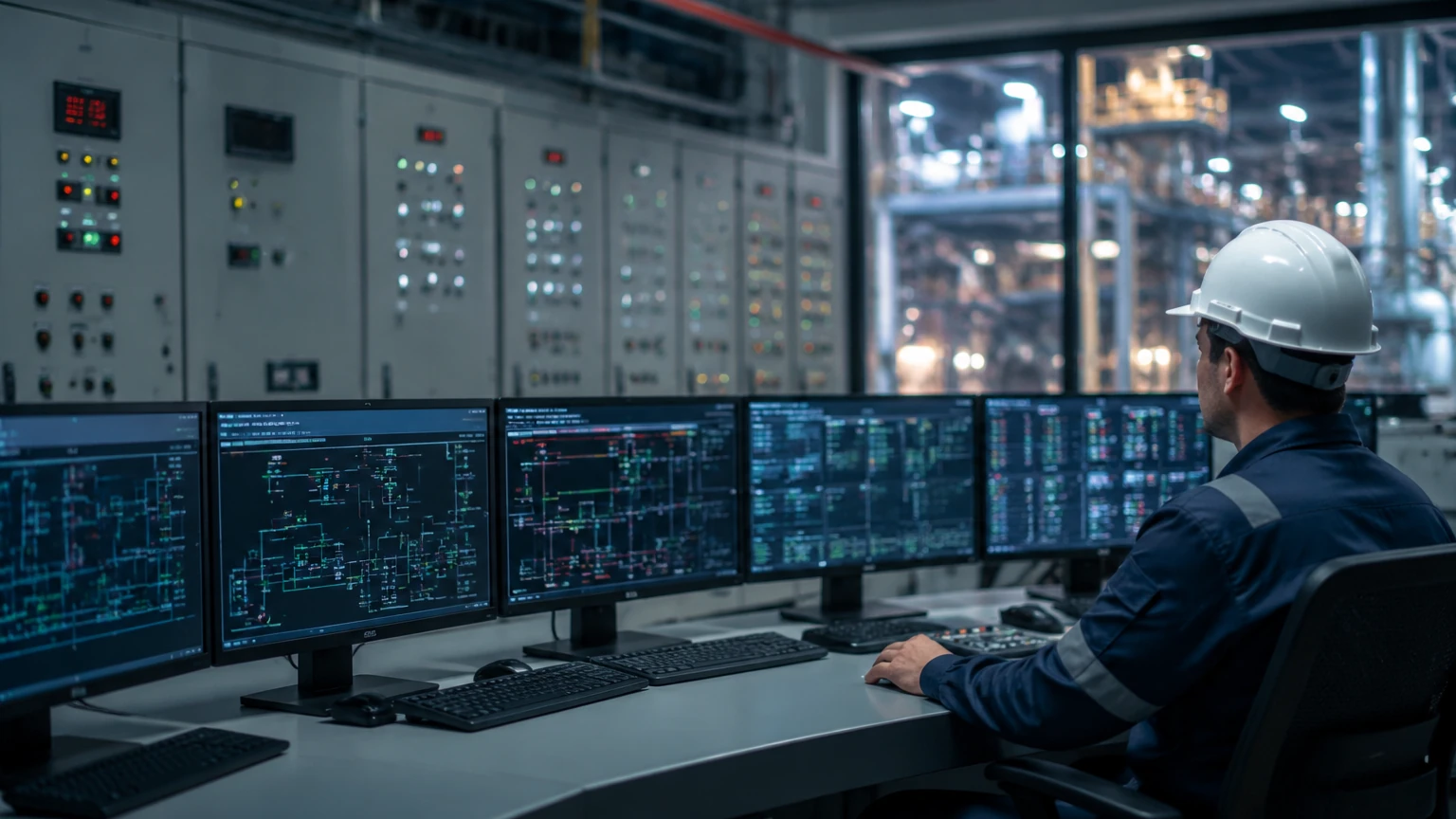
In modern industrial processing, the management of risk is not merely an operational preference but a regulatory and ethical necessity. Safety instrumentation systems (SIS) represent the final automated layer of defense in a process plant, designed to prevent or mitigate hazardous events by taking the process to a "safe state" when predetermined conditions are violated. Whether in chemical manufacturing, oil and gas refining, or large-scale water treatment, the reliability of level measurement within these systems is critical to preventing overfills, dry runs, and catastrophic vessel failures.
The Role of Level Measurement in Safety Instrumentation Systems
A safety instrumentation system is composed of three primary elements: sensors, logic solvers, and final control elements. In the context of level measurement, the sensor—such as a radar level meter or ultrasonic transmitter—detects a process deviation (e.g., a tank level exceeding a high-high threshold). The logic solver, typically a safety-rated PLC, processes this signal and determines if the risk threshold has been met. If so, it triggers the final control element, usually an automated safety shut-off valve or a pump power-cut, to neutralize the threat.
For an SIS to be effective, it must be independent of the Basic Process Control System (BPCS). While the BPCS manages day-to-day operations to keep the process within efficient parameters, the SIS remains dormant until a safety limit is breached. This separation ensures that a failure in the control system does not simultaneously disable the safety protection. For engineers designing these loops, selecting the correct measurement technology is the first step in achieving the required Safety Integrity Level (SIL).
Core Measurement Principles for SIS Applications
Before selecting an instrument for a safety-critical application, it is essential to understand the physical principles governing the measurement. In the B2B industrial sector, Welk provides several technologies that are commonly integrated into safety instrumentation systems.
Radar Level Measurement (Guided and Non-Contact)
Radar technology relies on the emission of electromagnetic pulses. In non-contact radar, these pulses are broadcast from an antenna, reflect off the liquid surface, and return to the sensor. Guided Wave Radar (GWR) utilizes a physical probe to direct the pulse. The time-of-flight (ToF) between emission and reception is used to calculate the distance.
* Safety Advantage: Radar is largely unaffected by changes in process pressure, temperature, or the presence of vapors and dust. This makes it a highly reliable choice for SIL 2 and SIL 3 loops where consistent performance under varying conditions is mandatory.
Ultrasonic Level Measurement
Ultrasonic sensors emit high-frequency sound waves. These waves travel through the air gap, reflect off the medium, and return to the transducer. The distance is calculated based on the speed of sound in the headspace.
* Safety Advantage: It is a cost-effective, non-contact solution for atmospheric tanks. However, because the speed of sound varies with air temperature and gas composition, integrated temperature compensation is required for safety-critical accuracy.
Hydrostatic Pressure Measurement
This principle measures the head pressure exerted by a liquid column. The pressure ($P$) is proportional to the height of the liquid ($h$), the density of the fluid ($
ho$), and gravity ($g$), expressed as $P =
ho gh$.
* Safety Advantage: Hydrostatic transmitters are robust and have no moving parts. They are often used as redundant secondary sensors in safety loops to provide a diverse measurement technology alongside radar.
Selection Criteria for SIS Level Instruments
When evaluating instruments for safety instrumentation systems, engineers must look beyond standard performance specifications. The following criteria are paramount:
1. Safety Integrity Level (SIL) Certification: Instruments should ideally be certified by a third party (such as exida or TÜV) according to IEC 61508. This certification provides the necessary PFDavg (Average Probability of Failure on Demand) data required for safety loop calculations.
2. Diagnostics: An SIS sensor must be capable of self-diagnostics. It should be able to detect internal hardware failures, signal loss, or probe fouling and communicate a "fail-safe" signal (typically <3.6 mA or >21 mA) to the logic solver.
3. Proof Test Coverage: The ease with which an operator can verify the instrument’s functionality without removing it from the process is a significant factor in long-term safety maintenance.
4. Redundancy and Voting: Depending on the risk, a 1oo2 (one out of two) or 2oo3 (two out of three) architecture may be required. This involves using multiple sensors to ensure that a single instrument failure does not cause a false trip or, worse, a failure to trip.
Practical Selection Table for SIS Level Technologies
| Technology | Typical SIL Capability | Ideal Application | Major Limitation |
| :— | :— | :— | :— |
| Guided Wave Radar | SIL 2 / SIL 3 | High-pressure boilers, volatile chemicals | Probes can be affected by heavy coating |
| Non-contact Radar | SIL 2 / SIL 3 | Corrosive liquids, large storage tanks | Sensitive to extremely low dielectric media |
| Ultrasonic | SIL 1 / SIL 2 | Water treatment, open channels | Affected by heavy foam and vacuum |
| Hydrostatic | SIL 2 | Constant density liquids, deep wells | Density changes cause measurement errors |
| Magnetic Switches | SIL 2 / SIL 3 | High/Low level alarms, secondary backup | Mechanical wear over long periods |
Installation Considerations for Safety Loops
The physical installation of level instruments in safety instrumentation systems requires stricter adherence to engineering standards than standard control installations. For a detailed look at hardware options and technical drawings, engineers can visit the Main Page for comprehensive product documentation.
* Physical Separation: Whenever possible, the SIS level sensor should be installed in a different nozzle or stilling well than the BPCS sensor. This prevents a single physical blockage or localized turbulence from affecting both the control and safety measurements.
* Environmental Protection: In outdoor installations, sunshades should be used to prevent electronic overheating, which can accelerate the failure rate of the components.
* Stilling Wells: For radar and ultrasonic installations in agitated tanks, the use of stilling wells (typically 50 mm to 100 mm in diameter) is recommended to provide a calm surface for measurement, thereby increasing the signal-to-noise ratio and the reliability of the safety trip.
* Mounting Position: Ensure that the "dead zone" or "blocking distance" of the sensor is accounted for. If the maximum high-high alarm level is within the sensor's dead zone, the SIS may fail to detect an overfill.
Limitations and Common Risks
Even with high-quality instrumentation from manufacturers like Welk, safety instrumentation systems are subject to limitations.
Systematic Failures: These are failures related to the design, installation, or operation of the system. For example, selecting an ultrasonic sensor for a tank that develops heavy foam is a systematic error. The sensor may function perfectly according to its design but fail to see the liquid level through the foam.
Random Hardware Failures: These are unpredictable failures resulting from the degradation of electronic or mechanical components. While these cannot be entirely eliminated, they are quantified using the Safe Failure Fraction (SFF). An instrument with a high SFF is more likely to fail in a way that alerts the system rather than failing "dangerously undetected."
Common Cause Failures (CCF): This occurs when multiple redundant sensors fail due to the same external factor, such as a localized power surge or a shared process connection becoming plugged. Utilizing diverse technologies (e.g., one radar and one hydrostatic transmitter) is a common strategy to mitigate CCF.
Frequently Asked Questions (FAQs)
Q: Can I use a standard level transmitter in an SIS loop?
A: While it is technically possible if the device has "proven-in-use" data, it is highly recommended to use instruments specifically certified for SIL 2 or SIL 3 applications. These devices have undergone rigorous assessment of their failure modes and diagnostic capabilities.
Q: What is the difference between a 1oo1 and a 1oo2 architecture?
A: A 1oo1 (one out of one) architecture relies on a single sensor. If it fails, the safety function is lost. A 1oo2 (one out of two) architecture uses two sensors; if either sensor detects a hazard, the system trips. This increases safety but also increases the likelihood of a "nuisance trip" (a trip when no actual hazard exists).
Q: How often should SIS level meters be calibrated?
A: Calibration frequency is determined by the "Proof Test Interval" defined in the safety requirement specification (SRS). This is calculated based on the desired SIL and the failure rate of the instrument. Common intervals range from 12 months to 5 years.
Q: Does foam affect all SIS level sensors?
A: No. While ultrasonic sensors are significantly hindered by foam, high-frequency radar (especially Guided Wave Radar) can often penetrate foam to measure the true liquid level. However, the type and density of the foam must be analyzed during the design phase.
Summary Checklist for Engineers
To ensure the integrity of safety instrumentation systems, the following steps should be verified before commissioning:
* Confirm that the instrument’s SIL rating matches or exceeds the loop requirement.
* Verify that the process wetted materials are compatible with the medium to prevent premature sensor failure.
* Ensure that the logic solver is programmed to recognize the specific failure current (e.g., 21.5 mA) of the transmitter.
* Document the baseline measurement and perform a physical trip test to validate the entire loop from sensor to valve.
* Establish a clear maintenance schedule for periodic proof testing as required by IEC 61511.
By following these technical guidelines and selecting robust measurement technologies, industrial facilities can maintain high safety standards while optimizing operational uptime.