Powder Level Sensors
Powder Level Sensors
In industrial automation, the measurement of bulk solids and powders presents a unique set of challenges compared to liquid level monitoring. From fine pharmaceutical ingredients to heavy mining ores, the physical properties of powders—such as dust generation, low dielectric constants, and the formation of irregular surfaces—require specialized sensing technologies. Selecting the correct powder level sensors is critical for maintaining inventory accuracy, preventing silo overfills, and ensuring the continuous flow of production lines.
As a professional manufacturer of industrial level measurement instruments, Welk provides a range of solutions designed to handle these complexities. Whether the application involves high-temperature fly ash or food-grade flour, understanding the underlying physics of measurement is the first step toward a reliable installation.
Understanding the Complexity of Powder Level Measurement
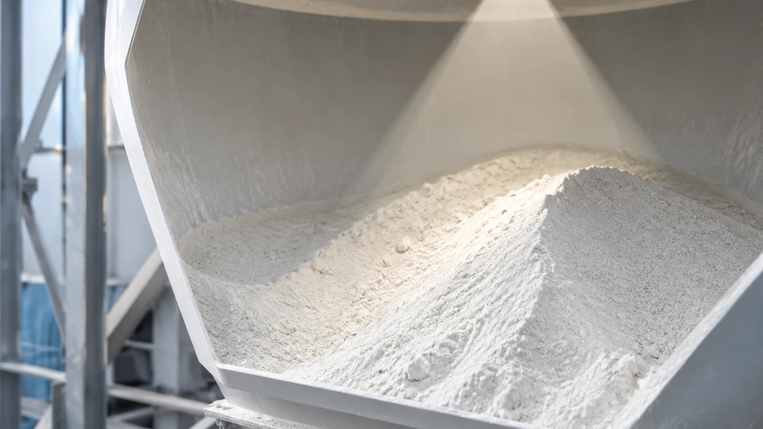
Unlike liquids, which maintain a horizontal surface, powders are characterized by an "angle of repose." When material is fed into a silo, it forms a cone; when it is discharged, it forms a funnel (or "rat-hole"). This means a single-point measurement may not always represent the true volume of the container. Furthermore, powders often contain significant amounts of entrained air, which lowers the effective dielectric constant ($ε_r$) of the material, making it harder for certain sensors to detect the surface.
Environmental factors also play a significant role. Heavy dust clouds created during filling cycles can attenuate ultrasonic waves or scatter light-based sensors. Additionally, powders can be abrasive, corrosive, or prone to static buildup, all of which influence the choice between contact and non-contact measurement methods.
Core Measurement Principles for Powder Level Sensors
To select the appropriate instrument, engineers must evaluate the measurement principle that best suits the material's physical properties and the vessel's geometry.
Radar Level Measurement (Non-Contact)
Radar technology is widely considered the gold standard for continuous powder level measurement. It operates on the Time of Flight (ToF) principle, where the sensor emits high-frequency electromagnetic pulses (usually in the 26 GHz or 80 GHz range). These pulses travel to the material surface, reflect, and return to the sensor. The distance is calculated based on the time elapsed.
* 80 GHz Technology: Modern powder level sensors often utilize the 80 GHz frequency. The shorter wavelength allows for a much narrower beam angle (as small as 3 degrees). This is crucial in narrow silos or vessels with internal obstructions like ladders or agitators, as it minimizes false reflections. The high frequency also provides better penetration through heavy dust and a stronger reflection from materials with low dielectric constants.
* Advantages: No moving parts, unaffected by dust, temperature, or pressure changes, and highly accurate (up to ±2 mm).
Guided Wave Radar (Contact)
Guided Wave Radar (GWR) also uses electromagnetic pulses, but instead of broadcasting them through the air, it guides them along a probe (usually a stainless steel cable or rod). The pulse reflects when it encounters a change in the dielectric constant at the material surface.
* Application in Powders: GWR is exceptionally effective for powders with very low dielectric constants because the probe concentrates the energy of the pulse. However, in tall silos, the downward "pull" force exerted by the settling powder on the cable can be immense (several tons), requiring heavy-duty sensors and reinforced silo roofs.
Ultrasonic Level Measurement
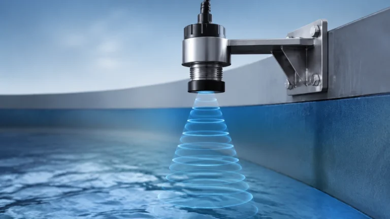
Ultrasonic sensors emit high-frequency sound waves. The time it takes for the echo to return determines the distance. While cost-effective, ultrasonic sensors have significant limitations in powder applications. Sound waves are easily absorbed by soft powders and scattered by heavy dust clouds. They are generally reserved for non-dusty, large-grained bulk solids or short-range applications.
Point Level Detection: Rotary and Vibrating Sensors
For applications that only require high-level or low-level alarms (rather than a continuous 0-100% reading), point level sensors are used.
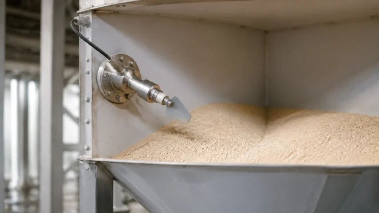
* Rotary Paddle Sensors: A small motor slowly rotates a paddle. When the powder reaches the paddle, it stalls the motor, triggering a switch. These are robust and unaffected by the electrical properties of the material.
* Vibrating Level Switches: These sensors use a tuning fork or a single rod that vibrates at its resonant frequency. When covered by material, the vibration is dampened, which the electronics detect as a level change. These are ideal for fine powders and can be designed to be extremely sensitive to low-density materials.
Selection Criteria for Powder and Bulk Solid Applications
When evaluating powder level sensors, several technical parameters must be confirmed to ensure long-term reliability:
1. Dielectric Constant ($ε_r$): This is the most critical factor for radar and capacitance sensors. Materials like plastic pellets have low $ε_r$ (~1.5 to 2.0), requiring high-sensitivity radar or GWR. Materials with higher moisture content are easier to detect.
2. Dust Levels: If the process involves pneumatic conveying or fine milling, dust will be constant. In these cases, non-contact radar is preferred over ultrasonic technology.
3. Process Temperature and Pressure: High-pressure silos or high-temperature processes (like cement kilns) require sensors with specialized seals and thermal decoupling.
4. Vessel Geometry: The height-to-width ratio of the silo and the presence of internal structures dictate the required beam angle of the sensor.
5. Material Abrasiveness: For highly abrasive materials, non-contact sensors are preferred to avoid mechanical wear on probes or paddles.
Comparison Table: Selecting the Right Powder Level Sensor
| Technology | Best For | Dust Tolerance | Max Range (Typical) | Contact/Non-Contact |
| :— | :— | :— | :— | :— |
| 80 GHz Radar | Fine powders, narrow silos, high accuracy | Excellent | Up to 120m (393 ft) | Non-Contact |
| Guided Wave Radar | Low dielectric materials, small bins | Good | Up to 30m (98 ft) | Contact |
| Ultrasonic | Large grains, low-dust environments | Poor | Up to 15m (49 ft) | Non-Contact |
| Rotary Paddle | High/Low level alarms, robust solids | Excellent | N/A (Point) | Contact |
| Vibrating Fork | Fine powders, light bulk solids | Excellent | N/A (Point) | Contact |
For more detailed specifications on specific models and their application ranges, you may visit the Main Page of our technical catalog.
Installation Guidelines and Best Practices
Proper installation is just as important as selecting the right technology. Even the most advanced radar sensor will fail if it is poorly positioned.
* Avoid the Fill Stream: Never mount a sensor directly in the path of the incoming material. This causes excessive noise in radar signals and can physically damage contact probes.
* Positioning for Angle of Repose: In a circular silo, the optimal mounting position for a continuous level sensor is typically 1/6 to 1/4 of the diameter away from the side wall. This provides a representative average of the material cone.
* Nozzle Design: For non-contact radar, the nozzle should be as short as possible. If the nozzle is long, the radar beam might reflect off the nozzle walls before reaching the material. If a long nozzle is unavoidable, an 80 GHz sensor with a narrow beam is required.
* Aiming Flanges: Because powders form cones, the signal often reflects away from the sensor. Using an adjustable aiming flange allows the technician to tilt the sensor toward the middle of the material slope, maximizing the return signal strength.
Common Limitations and Troubleshooting
Engineers should be aware of the following limitations when deploying powder level sensors:
* Signal Blocking: In very tall, narrow silos, the "beam spread" of a 26 GHz radar might hit the silo walls, causing false "high level" readings. Switching to a narrower beam 80 GHz unit usually resolves this.
* Bridging and Caking: If a powder is sticky or hygroscopic, it may build up on the sensor face or the GWR probe. Many modern radar sensors feature a "mapping" function that allows the software to ignore static reflections from buildup, but significant caking may still require a sensor with a PTFE or specialized flush-mount antenna.
* Static Discharge: The movement of dry powders can generate significant static electricity. Sensors used in these environments must be properly grounded and, in many cases, certified for use in explosive dust atmospheres (ATEX/IECEx).
Frequently Asked Questions (FAQs)
Q: Can one sensor measure both the level and the volume of a powder?
A: A level sensor measures distance. To calculate volume, the controller or PLC must use a strapping table or a mathematical formula based on the silo's dimensions and the material's estimated angle of repose. For high-precision volume measurement in very large silos, multi-point 3D scanners are sometimes used, though they are significantly more expensive than standard radar.
Q: How does bulk density affect measurement?
A: For radar and ultrasonic sensors, bulk density has little direct effect. However, for vibrating level switches, the material must be dense enough to dampen the vibration. Very light powders (less than 10 g/L) may require specialized, high-sensitivity vibrating rods.
Q: Is maintenance required for non-contact radar in dusty silos?
A: Generally, no. Most high-frequency radar sensors are designed to be self-cleaning or can be equipped with an air-purge connection to blow dust off the lens if it becomes an issue. This makes them much lower maintenance than mechanical systems.
Conclusion
Selecting the right powder level sensors requires a balance between process requirements, material characteristics, and budget. While point-level switches like rotary paddles offer a robust solution for simple overfill protection, the transition toward 80 GHz non-contact radar has provided industrial operators with unprecedented accuracy and reliability in continuous monitoring. By considering the dielectric constant, dust levels, and vessel geometry, engineers can implement a measurement solution that reduces downtime and optimizes inventory management.
For assistance with specific application engineering or to review our full range of measurement technologies, please refer to our Main Page for comprehensive product support and selection tools.