Thermal Mass Flow Meters
Thermal Mass Flow Meters
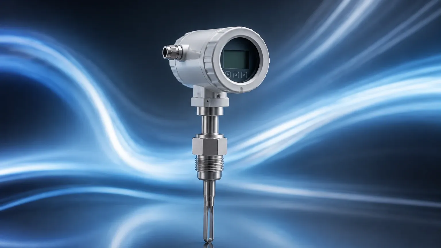
In the landscape of industrial process control, the accurate measurement of gas flow is as critical as monitoring liquid levels. Thermal mass flow meters (TMFMs) have emerged as a primary technology for measuring the mass flow rate of gases directly, without the need for additional pressure or temperature compensation. Unlike volumetric flow meters, which require complex calculations to account for gas density changes, thermal mass flow meters leverage the thermal properties of the fluid to provide a precise mass-based reading. This makes them indispensable in applications ranging from compressed air management to wastewater treatment aeration and natural gas monitoring.
Understanding Thermal Mass Flow Measurement Principles
Thermal mass flow meters operate based on the principle of thermal dispersion or the "King’s Law" of heat transfer. The fundamental concept is that a moving fluid will extract heat from a heated object at a rate proportional to the mass flow rate of that fluid.
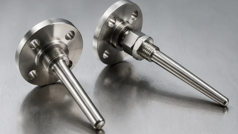
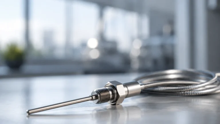
In a typical industrial thermal mass flow meter, the sensor probe contains two Resistance Temperature Detectors (RTDs). These sensors are typically constructed of platinum and are protected within robust metal thermowells.
1. The Reference Sensor: This RTD measures the actual temperature of the process gas.
2. The Active (Heated) Sensor: This RTD is supplied with a controlled amount of electrical power to maintain a specific temperature differential (ΔT) above the reference sensor.
As gas flows past the heated sensor, molecules carry away heat energy. To maintain the constant temperature differential, the electronic transmitter must increase the power supplied to the heated sensor. This electrical power requirement is directly proportional to the mass flow rate of the gas. Because mass flow is determined by the number of molecules passing the sensor, the measurement remains accurate regardless of fluctuations in process pressure or temperature, provided the gas composition remains constant.
Key Advantages in Industrial Applications
Thermal mass flow meters offer several distinct advantages over traditional differential pressure (DP) or turbine meters:
* Direct Mass Measurement: They provide mass flow data (e.g., kg/h or Nm³/h) without requiring external pressure and temperature transmitters.
* High Turndown Ratio: TMFMs can accurately measure very low flow velocities (down to 0.1 m/s) while maintaining a wide range, often exceeding 100:1.
* Low Pressure Drop: Because the sensors are small and often involve an insertion probe or a full-bore design with minimal obstruction, they do not cause significant energy loss in the piping system.
* No Moving Parts: The absence of mechanical components reduces wear and tear, making them suitable for dirty gas applications where mechanical meters would fail.
For engineers evaluating comprehensive instrumentation suites, including level and flow solutions, it is beneficial to Review product options and application support to ensure compatibility across the process control architecture.
Selection Criteria for Thermal Mass Flow Meters
Choosing the correct thermal mass flow meter requires a detailed understanding of the process environment. The two primary configurations are insertion meters and inline meters.
Comparison Table: Insertion vs. Inline Thermal Mass Flow Meters
| Feature | Insertion Meters | Inline Meters |
| :— | :— | :— |
| Pipe Size Range | 50 mm to 6000 mm | 6 mm to 100 mm |
| Installation | Flanged or compression fitting through a nozzle | Threaded or flanged connection within the pipe run |
| Accuracy | Typically ±1.0% to 1.5% of reading | Typically ±0.5% to 1.0% of reading |
| Maintenance | Can be removed via a hot-tap valve without shutdown | Requires process shutdown for removal |
| Primary Use Case | Large ducts, stacks, and large diameter pipes | Small diameter process lines and laboratory gas feeds |
When selecting a meter, the gas composition is the most critical variable. Since the meter is calibrated for the specific thermal conductivity and heat capacity of a particular gas (e.g., Nitrogen, Carbon Dioxide, or Methane), any change in the gas mixture will result in measurement errors. If the process involves a variable gas mixture, such as biogas, the meter must be programmed with the specific gas components to maintain accuracy.
Installation Best Practices and Straight Run Requirements
To achieve the specified accuracy, thermal mass flow meters require a fully developed flow profile. Turbulent or swirling flow caused by elbows, valves, or reducers can significantly distort the readings.
Straight Pipe Requirements
Standard installations generally require a minimum of 20 diameters (20D) of straight pipe upstream of the sensor and 10 diameters (10D) downstream. If these distances are not available, flow conditioners (such as perforated plates or honeycomb structures) must be installed to stabilize the flow profile.
Orientation and Positioning
* Vertical vs. Horizontal: For dry gases, the orientation is generally flexible. However, in horizontal pipes, the sensor should ideally be installed at the 2 o'clock or 10 o'clock position to avoid sediment at the bottom and moisture/condensate at the top.
* Insertion Depth: For insertion meters, the sensor tip must be located at the point of average velocity, which is typically at the center of the pipe for turbulent flow. Incorrect insertion depth is a leading cause of measurement inaccuracy in large-scale industrial ducts.
Limitations and Operational Considerations
While thermal mass flow meters are highly versatile, they are not universal solutions. Engineers must be aware of the following limitations:
1. Moisture and Condensate: TMFMs are sensitive to moisture. If water droplets hit the heated sensor, the meter will interpret the rapid cooling as a massive spike in gas flow. For applications with high humidity, such as digester gas or compressed air before a dryer, water traps or heated sensors are necessary.
2. Gas Composition Changes: As mentioned, the calibration is gas-specific. A meter calibrated for pure Air will not provide accurate readings for Argon or Helium without recalibration or the use of correction factors.
3. Coating and Contamination: While the lack of moving parts helps, a thick buildup of oil, grease, or dust on the sensor probes can insulate the RTDs, slowing the response time and introducing a negative bias in the flow data. Regular inspection and cleaning are recommended in "dirty" gas environments.
4. Fluid Phase: These meters are strictly for gases. They cannot be used for liquid flow measurement or steam, as the thermal properties of these fluids exceed the design parameters of standard gas-phase thermal sensors.
Frequently Asked Questions (FAQs)
Q: Do thermal mass flow meters need to be recalibrated annually?
A: While the sensors are inherently stable, many industrial standards (such as ISO 9001) or environmental regulations (for flare gas monitoring) require annual calibration verification. Many modern meters offer an internal "dry check" or self-diagnostic feature to verify the electronics and sensor integrity without removing the meter from the line.
Q: Can I use a thermal mass flow meter for oxygen service?
A: Yes, but the meter must be specifically cleaned for oxygen service to remove all hydrocarbons and oils. Furthermore, the materials of construction must be compatible with high-concentration oxygen to prevent combustion risks.
Q: How does the response time of a thermal meter compare to other technologies?
A: Thermal meters typically have a response time of 1 to 2 seconds. While this is sufficient for most process control loops, it may be slower than a differential pressure meter or a Coriolis meter in applications requiring instantaneous sub-second response.
Integration with Industrial Level Measurement
In many industrial sectors, such as chemical processing and water treatment, flow measurement and level measurement go hand-in-hand. For instance, in a chemical storage facility, level sensors monitor the volume of liquid in a tank, while thermal mass flow meters monitor the nitrogen blanketing gas used to prevent oxidation or explosion.
Integrating these measurements into a single automation platform requires reliable hardware. Whether you are managing tank levels with radar or monitoring gas consumption with thermal technology, selecting instruments from a professional manufacturer ensures long-term stability. For more information on industrial instrumentation and to explore technical specifications, visit the Main Page of the primary technical resource.
Conclusion
Thermal mass flow meters provide a robust, accurate, and cost-effective solution for gas flow measurement across diverse industrial applications. By understanding the underlying thermal dispersion principles and adhering to strict installation guidelines—particularly regarding straight pipe runs and gas composition—engineers can achieve high-precision monitoring. While limitations regarding moisture and gas purity must be managed, the benefits of direct mass measurement and high turndown make the thermal mass flow meter a cornerstone of modern industrial process efficiency.