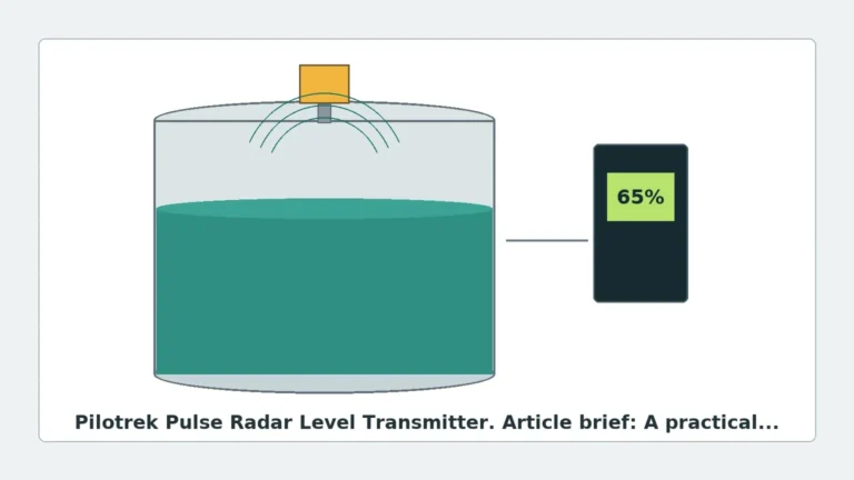
Guided Wave Radar Liquid Level Transmitter
Guided Wave Radar Liquid Level Transmitter: A Practical Engineering Guide
In the field of industrial process automation, the accuracy of level measurement is a critical factor for safety, efficiency, and inventory management. Among the various technologies available, the guided wave radar liquid level transmitter has emerged as a preferred solution for challenging environments where traditional non-contact methods may struggle. Based on Time Domain Reflectometry (TDR) technology, these instruments provide a direct and stable measurement by guiding electromagnetic pulses along a physical probe.
This guide explores the fundamental principles, selection criteria, and installation requirements for guided wave radar (GWR) systems, providing engineers and procurement professionals with the technical context needed to integrate these devices into industrial workflows.
1. Measurement Principles of Guided Wave Radar
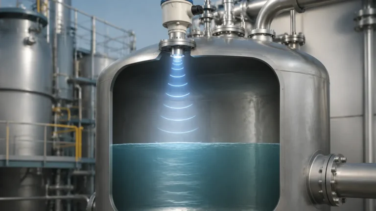
The operation of a Radar Level Meters system using guided wave technology is based on the principle of Time Domain Reflectometry (TDR). Unlike non-contact radar, which broadcasts waves through the air, a GWR transmitter sends low-energy electromagnetic pulses down a metallic probe (the waveguide).
The Reflection Mechanism
When these pulses reach the surface of the liquid being measured, a portion of the pulse energy is reflected back to the transmitter electronics. This reflection occurs due to the change in the dielectric constant ($ε_r$) between the upper medium (usually air or gas) and the lower medium (the liquid).
The transmitter measures the time-of-flight—the interval between the emission of the pulse and the reception of the reflected signal. Since the speed of electromagnetic waves is constant, the distance to the liquid surface can be calculated with high precision.
The Role of the Dielectric Constant
The dielectric constant of the liquid is the primary factor determining the strength of the reflection.
- High Dielectric Liquids: Water (ε_r ≈ 80) reflects a very strong signal, making measurement straightforward.
- Low Dielectric Liquids: Hydrocarbons and oils (ε_r ≈ 1.4 to 2.5) reflect a much weaker signal. In these cases, the pulse may partially penetrate the surface, allowing the transmitter to detect the interface between two different liquids (e.g., oil over water).
2. Advantages Over Non-Contact Radar
While both technologies fall under the umbrella of radar level measurement, the guided wave radar liquid level transmitter offers specific advantages in industrial applications:
1. Signal Integrity: By confining the signal to a probe, the energy is not dissipated over a wide area. This makes GWR ideal for small tanks or vessels with internal obstructions like agitators or baffles.
2. Turbulence and Foam: Because the signal is guided, surface turbulence, ripples, or moderate foam layers have less impact on measurement reliability compared to non-contact radar.
3. Vapor and Dust: GWR is virtually unaffected by heavy steam, dust, or vapor layers in the tank headspace, as the waveguide ensures the pulse reaches the liquid surface without significant attenuation.
4. Interface Measurement: GWR is uniquely capable of measuring both the total level and the interface level between two immiscible liquids, such as the water level at the bottom of an oil tank.
3. Probe Selection and Configurations
Choosing the correct probe type is essential for the performance of the transmitter. Probes are generally categorized into three designs:
Single Rod / Single Cable
This is the most common and versatile probe type. It is easy to clean and resistant to material build-up. However, it is more sensitive to the proximity of the tank wall and internal obstructions. It is best suited for liquids with a dielectric constant greater than 1.9.
Twin Rod / Twin Cable
Consisting of two parallel conductors, this design creates a more concentrated electromagnetic field between the rods. It is better suited for liquids with lower dielectric constants than single-rod versions. The primary disadvantage is the risk of "bridging," where viscous liquids or solids get stuck between the rods, causing false readings.
Coaxial Probe
Similar to a coaxial cable, this probe features a central rod inside an outer pipe. The electromagnetic field is entirely contained within the pipe, providing the highest signal-to-noise ratio. It is unaffected by tank walls or internal obstructions and can measure liquids with very low dielectric constants (ε_r ≥ 1.4). However, it is prone to clogging if the liquid contains suspended solids or is highly viscous.
4. Practical Selection Table
| Application Type | Liquid Dielectric ($ε_r$) | Recommended Probe | Notes |
| :— | :— | :— | :— |
| Water-based liquids | > 10 | Single Rod / Cable | Standard choice for water treatment and chemicals. |
| Hydrocarbons / Oils | 1.9 to 10 | Twin Rod or Coaxial | Requires higher signal sensitivity. |
| Liquefied Gases | 1.4 to 1.9 | Coaxial | Coaxial provides the necessary signal focus. |
| Viscous / Dirty Liquids | > 5 | Single Rod | Minimizes risk of material build-up and clogging. |
| Interface Measurement | ε_r1 > 10, ε_r2 < 3 | Single Rod / Coaxial | Lower dielectric liquid must be on top. |
5. Installation Considerations and Constraints
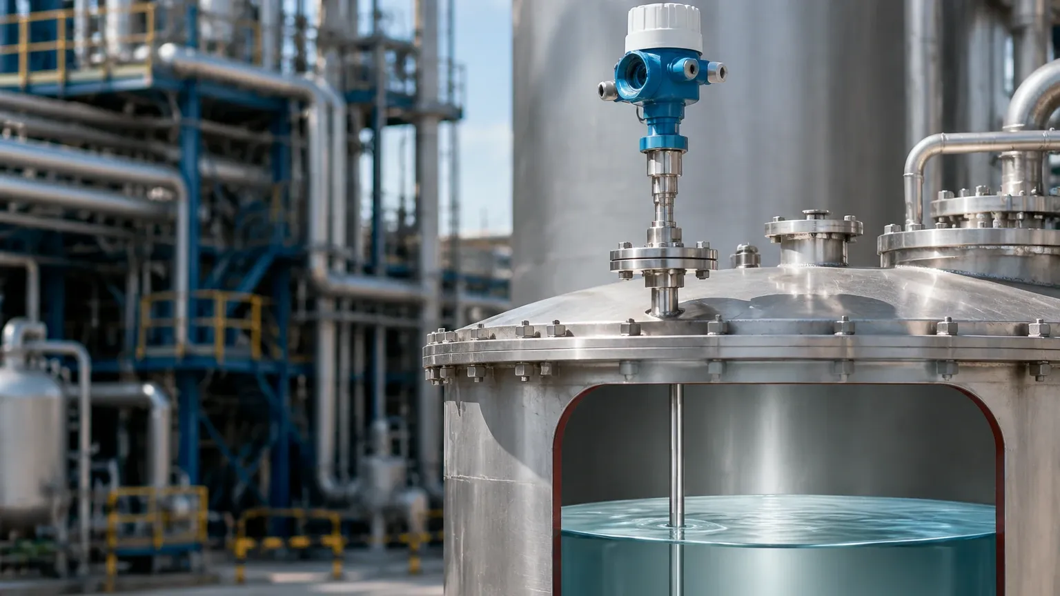
Successful deployment of a guided wave radar liquid level transmitter requires adherence to specific installation geometry to avoid signal interference.
Nozzle Dimensions
The mounting nozzle should be as short and wide as possible. For single rod probes, the nozzle diameter should ideally be at least 50mm (2 inches). If the nozzle is too narrow or too long, it can create a large "ringing" effect at the top of the probe, leading to an increased upper dead zone.
Clearance and Obstructions
- Wall Distance: Single rod probes must be installed at a minimum distance from the tank wall (typically 100mm to 300mm depending on the probe length) to prevent the signal from interacting with the tank shell.
- Internal Obstacles: Ensure the probe does not touch or come too close to agitators, heating coils, or ladders. If contact is unavoidable, a coaxial probe or a bypass chamber (bridle) should be used.
Dead Zones (Blocking Distance)
Every GWR transmitter has an upper and lower dead zone.
- Upper Dead Zone: The area at the very top of the probe where measurement is not possible due to the initial pulse launch. This typically ranges from 50mm to 200mm (2 to 8 inches).
- Lower Dead Zone: The area at the tip of the probe where the signal is lost. This is usually around 50mm (2 inches).
Engineers must ensure that the maximum and minimum process levels fall within the "active" measuring range of the probe.
6. Limitations and Application Risks
While highly reliable, GWR technology has specific limitations that must be managed:
* Coating and Build-up: While single rod probes handle coating better than others, extreme build-up of conductive material can attenuate the signal or cause a "virtual" level reading. Regular inspection or the use of specialized "heavy coating" algorithms may be required.
* Low Dielectric Sensitivity: If the liquid's dielectric constant is extremely low and the surface is turbulent, the reflected signal may fall below the detection threshold.
* Physical Stress: In tall tanks with high-velocity inflow or heavy agitation, flexible cable probes may sway. In such cases, the probe should be anchored to the bottom of the tank using a weight or a centering disk, ensuring the anchor is electrically isolated if necessary.
7. Frequently Asked Questions (FAQs)
Q: Can a guided wave radar transmitter be used in a plastic tank?
A: Yes, but since plastic is non-conductive, a single rod probe requires a metal flange or a large metal washer at the mounting point to act as a ground plane for the pulse launch. Alternatively, a coaxial probe can be used without a ground plane.
Q: Does the pressure or temperature in the tank affect the accuracy?
A: Generally, no. The speed of the electromagnetic pulse is not significantly affected by temperature or pressure changes. However, the physical materials of the transmitter (seals and probe insulation) must be rated for the process conditions. Extreme high-pressure steam can slightly slow the pulse, requiring a compensation factor in the transmitter settings.
Q: Is it possible to shorten the probe in the field?
A: Many cable-type GWR probes are designed to be field-cut to the exact length required. Rod-type probes can sometimes be cut, but this may require re-threading or specialized tools. Always consult the manufacturer's manual before modifying the probe length, as the transmitter's configuration must be updated to reflect the new length.
8. Conclusion for International Buyers
When sourcing a guided wave radar liquid level transmitter for industrial projects, it is vital to provide the manufacturer with a complete process profile. This includes the chemical composition of the liquid, the dielectric constant, the operating temperature and pressure, and the tank's physical dimensions.
By understanding the relationship between the probe design and the medium's properties, engineers can select a Radar Level Meters solution that minimizes maintenance and maximizes uptime. Whether dealing with corrosive chemicals, volatile hydrocarbons, or simple water storage, GWR technology provides a robust, contact-based measurement that withstands the rigors of modern industrial environments.
Download Guided Wave Radar Liquid Level Transmitter as a PDF