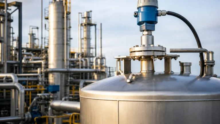
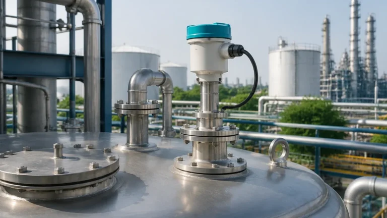
Radar Level Transmitter Use the Following Principle to Measure Level
Radar Level Transmitter Use the Following Principle to Measure Level
In the landscape of industrial automation and process control, precision in liquid and solid level measurement is paramount. Among the various technologies available, radar-based systems have emerged as a gold standard for reliability in challenging environments. To select the correct instrument for a specific application, engineers must understand that a radar level transmitter use the following principle to measure level: the transmission and reflection of high-frequency electromagnetic waves to determine the distance to a product surface.
This guide provides a comprehensive technical overview of radar measurement principles, frequency variations, selection criteria, and installation best practices for industrial professionals.
1. Core Measurement Principles
Radar level measurement is a "top-down" non-contact or contact method. Unlike hydrostatic transmitters that rely on pressure or ultrasonic sensors that use sound waves, radar utilizes electromagnetic energy, typically in the microwave spectrum.
A radar level transmitter use the following principle to measure level based on two primary modulation techniques: Pulse Radar and Frequency Modulated Continuous Wave (FMCW).
Time of Flight (ToF) and Pulse Radar
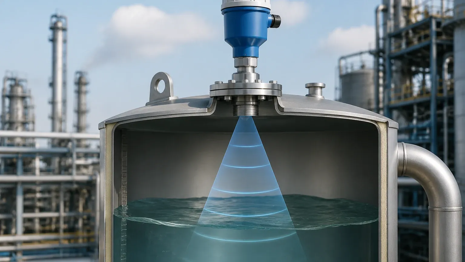
Pulse radar transmitters emit a short microwave pulse toward the medium. This pulse travels at the speed of light ($c$), hits the surface of the material, and is reflected back to the antenna. The instrument measures the time elapsed between the emission and the reception of the signal.
The distance ($D$) is calculated using the formula:
$$D = \frac{c \times t}{2}$$
Where:
* $c$ is the speed of light (approx. 300,000 km/s).
* $t$ is the measured transit time.
Because the speed of light is constant regardless of air temperature or pressure, pulse radar is highly stable in varying process conditions.
Frequency Modulated Continuous Wave (FMCW)
Modern high-precision Radar Level Meters often utilize FMCW technology. Instead of sending discrete pulses, the transmitter emits a continuous signal with a frequency that changes linearly over time (a frequency sweep).
When the signal is reflected from the surface and returns to the antenna, there is a frequency difference between the transmitted signal and the received signal. This frequency shift ($\Delta f$) is directly proportional to the distance. FMCW radar offers superior signal-to-noise ratios and is generally more accurate for complex applications involving turbulence or low-dielectric materials.
The Role of the Dielectric Constant (εr)
The ability of a radar signal to reflect off a surface depends on the dielectric constant of the medium. Materials with high dielectric constants (like water, $\varepsilon_r \approx 80$) reflect signals very strongly. Materials with low dielectric constants (like hydrocarbons or dry powders, $\varepsilon_r < 2$) allow most of the radar energy to pass through, reflecting only a small portion. Understanding the $\varepsilon_r$ of the process media is critical for selecting the correct antenna and frequency.
2. Frequency Bands and Their Applications
The frequency at which a radar level transmitter operates significantly impacts its beam angle, sensitivity, and ability to handle obstacles.
* C-Band (approx. 6 GHz): These transmitters have longer wavelengths and are less affected by foam, dust, or heavy vapors. However, they require larger antennas to maintain a narrow beam. They are often used in applications with heavy agitation.
* K-Band (approx. 26 GHz): This is the most common industrial frequency. It offers a balance between antenna size and beam focus. It is suitable for a wide range of liquids and solids in medium-sized tanks.
* W-Band (approx. 80 GHz): The current state-of-the-art in radar technology. The high frequency allows for a very narrow beam angle (often as low as 3°), which is ideal for tall, narrow silos or tanks with internal obstructions like agitators and heating coils. It also provides higher resolution for measuring low-dielectric liquids.
3. Contact vs. Non-Contact Radar
While the fundamental principle remains the same, the delivery of the signal differs between Guided Wave Radar (GWR) and Non-Contact Radar.
Guided Wave Radar (GWR)
GWR uses a physical probe (rod or cable) to guide the microwave signal to the surface. This is particularly effective for low-dielectric liquids and applications where the surface is turbulent or covered in foam. Since the energy is concentrated along the probe, signal loss is minimized.
Non-Contact Radar
Non-contact radar emits signals through the air via a horn or lens antenna. It is preferred for corrosive media, hygienic applications, or processes where the medium might damage or cling to a physical probe.
4. Selection Criteria for Industrial Applications
When specifying Radar Level Meters, engineers must evaluate the following technical parameters:
| Parameter | Consideration |
| :— | :— |
| Medium State | Is it a liquid, slurry, or solid? Solids require higher frequencies to handle uneven surfaces. |
| Dielectric Constant (εr) | If $\varepsilon_r < 1.5$, Guided Wave Radar or high-frequency FMCW radar is usually required. |
| Process Temperature | Standard units handle up to 150°C; specialized high-temp versions can exceed 400°C. |
| Process Pressure | Radar is unaffected by vacuum, but high-pressure vessels require specialized flange seals. |
| Vessel Geometry | Tall, narrow vessels favor 80 GHz radar to avoid wall interference. |
| Internal Obstructions | Agitators, ladders, and pipes can create false echoes. Narrow beam angles mitigate this. |
| Measurement Range | Standard radar can measure from 0.1 m up to 120 m (approx. 4 inches to 393 feet). |
5. Installation Guidelines and Constraints
Proper installation is critical to ensure the radar level transmitter functions according to its specified principle. Even the most advanced sensor will fail if the signal path is compromised.
The Dead Zone (Blind Zone)
Every radar transmitter has a "dead zone" near the antenna (typically 50 mm to 300 mm) where measurement is not possible. The vessel should never be filled into this zone, as the sensor will lose the signal or provide an error.
Nozzle Design
The mounting nozzle should be as short and wide as possible. If the nozzle is too long or narrow, the radar signal may reflect off the nozzle walls before reaching the process medium, creating a "ringing" effect that obscures the true level. For 80 GHz radar, this is less of a concern due to the narrow beam, but it remains a critical factor for 26 GHz units.
Beam Path and Obstacles
The radar beam spreads as it travels. Engineers must ensure the "footprint" of the beam at the bottom of the tank does not intersect with agitator blades, heating coils, or the tank wall. If obstructions are unavoidable, most modern transmitters offer "false echo suppression" software to map out and ignore these static reflections.
Orientation
The antenna should be mounted perpendicular to the liquid surface. For solids, where the material forms a cone (angle of repose), an aiming flange may be necessary to tilt the sensor and maximize signal return.
6. Limitations and Application Risks
While radar is versatile, it is not a universal solution. Certain conditions can interfere with the measurement principle:
1. Heavy Foam: While some radar frequencies can penetrate light foam, dense, thick foam (like shaving cream) can absorb the microwave signal entirely, leading to signal loss.
2. Condensation and Buildup: Heavy condensation or material buildup on the antenna lens can attenuate the signal. In these cases, a transmitter with a PTFE lens or a purging connection (using compressed air) should be used.
3. Extremely Low Dielectric Solids: Very light powders with high air content may not provide enough reflection for non-contact radar. Guided Wave Radar is often the better choice here.
4. Multiple Interfaces: If a tank contains two liquids (e.g., oil and water), non-contact radar will only see the top layer. Guided Wave Radar can often measure both the total level and the interface level.
7. Frequently Asked Questions (FAQ)
Q: Does vacuum affect radar level measurement?
A: No. Unlike ultrasonic sensors which require a medium (air) to transmit sound, radar uses electromagnetic waves which travel perfectly through a vacuum. This makes radar ideal for vacuum distillation columns.
Q: Can radar measure through a plastic tank lid?
A: Yes. If the tank is made of a non-conductive material like polyethylene (PE) or polypropylene (PP), a non-contact radar can often measure the level from outside the tank, looking through the roof. This is common in chemical storage applications.
Q: What is the difference between 2-wire and 4-wire radar transmitters?
A: 2-wire transmitters are loop-powered (the same two wires provide power and the 4-20mA signal), which simplifies wiring. 4-wire transmitters have separate power and signal circuits, allowing for higher power consumption, which is sometimes needed for high-performance signal processing or heated displays.
Q: How do I handle heavy dust in a grain silo?
A: Use a high-frequency (80 GHz) radar with a dust-resistant lens and a purging connection. The high frequency provides the power needed to penetrate dust clouds and reflect off the uneven grain surface.
8. Summary for Technical Buyers
Understanding that a radar level transmitter use the following principle to measure level—the measurement of time or frequency shift of electromagnetic waves—is the first step in successful instrumentation. By matching the frequency, antenna type, and installation method to the specific dielectric and physical properties of the media, industrial facilities can achieve maintenance-free, high-accuracy level control.
For most modern industrial applications, the trend is moving toward 80 GHz FMCW radar due to its narrow beam and high resolution. However, for applications involving heavy foam or very low dielectric constants, Guided Wave Radar remains a technically superior alternative. Always consult the manufacturer's dielectric tables and beam angle charts during the design phase to ensure long-term operational reliability.
Download Radar Level Transmitter Use the Following Principle to Measure Level as a PDF