Electronic Flow Meters
Electronic Flow Meters
In the landscape of modern industrial automation, the transition from mechanical to electronic flow measurement represents a significant leap in process control efficiency. Electronic flow meters utilize advanced sensor technology and digital signal processing to measure the linear, nonlinear, mass, or volumetric flow rate of liquids, gases, and steam. Unlike traditional mechanical meters that rely on moving parts subject to wear and tear, electronic variants offer enhanced precision, long-term stability, and the ability to integrate seamlessly into complex SCADA and PLC systems. For engineers and facility managers, understanding the nuances of these instruments is essential for optimizing resource management and ensuring safety across chemical, water treatment, and oil and gas sectors.
Measurement Principles of Electronic Flow Meters
The term "electronic flow meter" encompasses several distinct technologies, each operating on different physical principles. Selecting the appropriate technology requires a fundamental understanding of how these sensors interact with the process media.
Electromagnetic Flow Meters (Magmeters)
Electromagnetic meters operate based on Faraday’s Law of Induction. When a conductive liquid flows through a magnetic field generated by the meter, it produces a voltage proportional to its velocity.
* Formula: $E = B \cdot L \cdot v$, where $E$ is the induced voltage, $B$ is the magnetic field strength, $L$ is the distance between electrodes, and $v$ is the fluid velocity.
* Application: These are ideal for conductive liquids such as water, acids, and slurries. Because the sensor is non-intrusive and has no moving parts, there is zero pressure drop across the meter.
Ultrasonic Flow Meters
Ultrasonic technology typically uses two methods: Transit-Time and Doppler Effect.
* Transit-Time: This method measures the difference in time it takes for an ultrasonic signal to travel upstream versus downstream. The time difference is directly proportional to the flow velocity. It is most effective for clean liquids.
* Doppler Effect: This method reflects sound waves off particles or bubbles in the fluid. The frequency shift of the reflected signal determines the velocity. This is preferred for aerated liquids or slurries.
Vortex Flow Meters
Vortex meters utilize the Karman Vortex Street principle. As fluid flows past a bluff body (a non-streamlined object) placed in the flow stream, vortices are shed alternately on each side. The frequency of this shedding is proportional to the fluid velocity.
* Application: These are highly versatile, used for measuring steam, gases, and low-viscosity liquids. They are particularly valued in high-temperature applications where other electronic sensors might fail.
Coriolis Mass Flow Meters
Coriolis meters measure mass flow directly rather than volume. They consist of vibrating tubes; as fluid passes through, the Coriolis force causes the tubes to twist. The degree of twist is measured by sensors and converted into a mass flow rate.
* Application: These provide the highest accuracy (often up to ±0.1%) and are capable of measuring mass, density, and temperature simultaneously. They are the gold standard for custody transfer in the oil and gas industry.
Thermal Mass Flow Meters
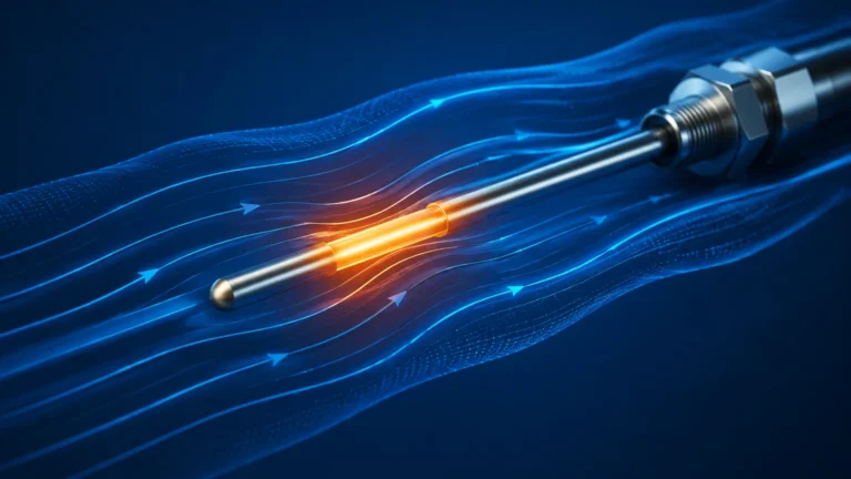
These meters measure the heat dissipation from a heated sensor immersed in the fluid. The rate of heat loss to the flowing media is proportional to the mass flow rate of the gas.
* Application: Primarily used for gas flow measurement, such as compressed air, nitrogen, or natural gas, especially in low-pressure systems.
Practical Selection Criteria
Choosing the right electronic flow meter involves balancing technical requirements with budget constraints. The following table provides a comparison of the most common electronic flow measurement technologies.
Selection Table: Comparison of Electronic Flow Technologies
| Technology | Typical Accuracy | Media Type | Pipe Size Range | Pressure Drop | Conductivity Required? |
| :— | :— | :— | :— | :— | :— |
| Electromagnetic | ±0.5% of rate | Conductive Liquids | 10 mm to 3000 mm | None | Yes (>5 μS/cm) |
| Ultrasonic (Transit) | ±1.0% to ±2.0% | Clean Liquids | 15 mm to 5000 mm | None | No |
| Vortex | ±1.0% (Liquid) | Liquid, Gas, Steam | 15 mm to 300 mm | Low to Medium | No |
| Coriolis | ±0.1% to ±0.2% | Liquids, Slurries | 2 mm to 300 mm | Medium | No |
| Thermal Mass | ±1.0% to ±2.0% | Gases | 15 mm to 1000 mm+ | Low | No |
When evaluating these options, engineers must also consider the "Turn-down Ratio," which is the ratio of the maximum flow to the minimum flow the meter can accurately measure. Electronic meters generally offer much higher turn-down ratios (e.g., 100:1) compared to mechanical orifice plates (e.g., 4:1).
Installation Considerations
The accuracy of electronic flow meters is heavily dependent on proper installation. Even the most sophisticated Coriolis or electromagnetic meter will yield unreliable data if installed in a turbulent or partially filled pipe.
1. Straight Pipe Runs
Most electronic flow meters require a specific length of straight pipe upstream and downstream to ensure a stable, laminar flow profile. A common rule of thumb is "10D Upstream and 5D Downstream," where D is the pipe diameter. If a valve or elbow is immediately before the meter, the required straight run may increase to 20D or 30D.
2. Full Pipe Condition
For electromagnetic and ultrasonic meters, the pipe must be completely full of liquid. If there is air or a vacuum at the top of the pipe, the meter will read incorrectly. To ensure a full pipe, it is best to install the meter on a vertical upward-flowing pipe or at the lowest point of a U-shaped pipe section.
3. Orientation and Grounding
* Electromagnetic Meters: Proper grounding is critical. The fluid, the meter, and the piping must be at the same electrical potential to prevent stray currents from interfering with the low-voltage signal generated by the sensor.
* Coriolis Meters: These are sensitive to external vibrations. They should be mounted on rigid supports to prevent mechanical noise from affecting the tube vibration measurement.
4. Signal Interference
Electronic flow meters transmit data via 4-20mA loops, Modbus, or HART protocols. To prevent electromagnetic interference (EMI), signal cables should be shielded and kept away from high-voltage power lines or variable frequency drives (VFDs).
Limitations and Common Risks
While electronic flow meters offer superior performance, they are not without limitations. Recognizing these risks early in the project phase can prevent costly downtime.
* Power Dependency: Unlike mechanical meters, electronic units require a stable power supply. In remote locations, this may necessitate solar power or battery-operated units with low-power consumption modes.
* Fluid Properties: Changes in fluid density, viscosity, or conductivity can affect certain technologies. For instance, if a magmeter is used with a non-conductive fluid like deionized water or oil, it will fail to produce a signal.
* Entrained Air: Bubbles in a liquid stream can cause significant errors in transit-time ultrasonic meters and vortex meters. In such cases, an air eliminator may be required upstream.
* Initial Cost: The CAPEX for electronic meters, especially Coriolis or high-precision electromagnetic models, is higher than mechanical alternatives. However, the Total Cost of Ownership (TCO) is often lower due to reduced maintenance and improved process yield.
As a professional manufacturer of industrial instrumentation, Welk provides a range of solutions that complement flow measurement systems. While flow meters track the movement of media, level measurement is equally critical for inventory and process safety. For comprehensive instrumentation support and to explore how level and flow data can be integrated for better process visibility, you may Review product options and application support on our Main Page.
Frequently Asked Questions (FAQs)
1. How often do electronic flow meters need calibration?
Calibration frequency depends on the industry and the criticality of the measurement. In regulated industries like pharmaceuticals or food and beverage, annual calibration is standard. In general water treatment applications, a check every 2 to 3 years may suffice. Many modern electronic meters feature "Self-Verification" diagnostics that can extend the time between physical calibrations.
2. Can electronic flow meters measure bidirectional flow?
Yes, many electronic technologies, specifically electromagnetic and ultrasonic meters, are inherently capable of measuring flow in both directions. This is particularly useful in water distribution networks or storage tank loading/unloading applications.
3. What is the difference between a compact and a remote transmitter?
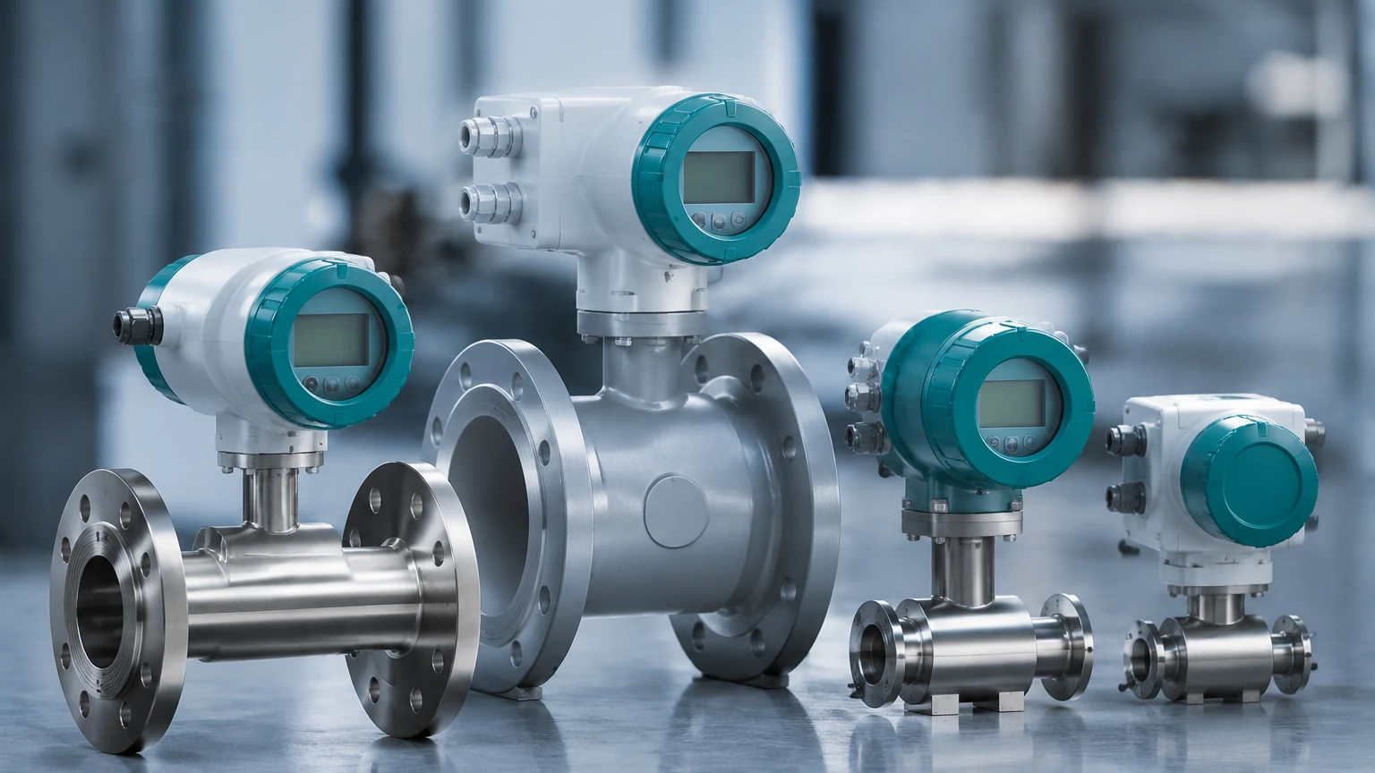
In a "Compact" version, the electronic transmitter is mounted directly on the sensor body. In a "Remote" version, the transmitter is mounted separately (often in a control room or on a wall) and connected to the sensor via a cable. Remote mounting is preferred for applications with high temperatures, high vibration, or limited accessibility.
4. Are electronic flow meters suitable for hazardous areas?
Yes, most manufacturers offer versions with ATEX, IECEx, or UL certifications for use in explosive atmospheres. These units utilize intrinsically safe circuits or explosion-proof housings to ensure safety.
Conclusion
Electronic flow meters are the backbone of modern industrial fluid management. By eliminating moving parts and leveraging digital processing, they provide the accuracy and reliability required for sophisticated automation. Whether it is the non-intrusive nature of ultrasonic sensors or the high-precision mass measurement of Coriolis meters, selecting the right technology depends on a thorough analysis of the fluid properties, pipe geometry, and environmental conditions. When paired with reliable level measurement instruments, these devices allow for total control over industrial process loops, reducing waste and enhancing operational safety.