Carbon Capture and Storage Systems
Carbon Capture and Storage Systems
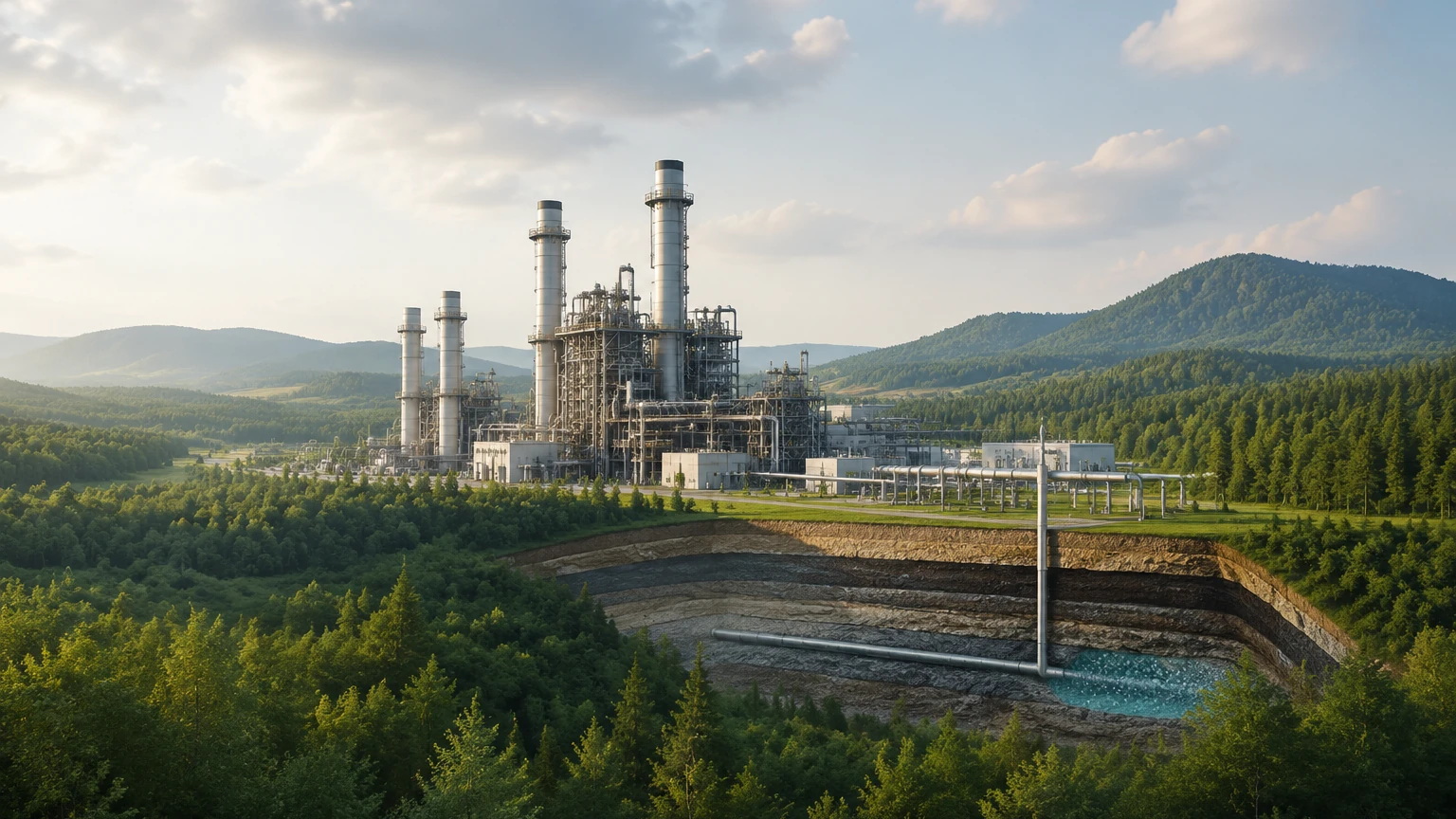
Carbon capture and storage systems (CCS) represent a critical infrastructure for industrial decarbonization, particularly in sectors such as power generation, cement manufacturing, and steel production. These systems involve the capture of carbon dioxide (CO2) from industrial flue gases, its compression and transport, and its eventual injection into deep geological formations for permanent storage. Throughout this complex process, precise level measurement is essential for maintaining operational safety, optimizing solvent efficiency, and ensuring the integrity of storage vessels.
In the context of carbon capture and storage systems, level instrumentation must withstand diverse chemical environments, from corrosive amine solvents to high-pressure supercritical CO2. Selecting the correct measurement technology requires a deep understanding of the physical properties of the media and the specific requirements of each process stage.
The Role of Level Measurement in Carbon Capture and Storage Systems
Level measurement in CCS is not merely about inventory management; it is a fundamental component of process control. In the capture phase, level sensors monitor the height of absorption liquids in columns to prevent flooding or dry-running of pumps. During transport and storage, they ensure that liquefied CO2 remains within safe volume limits in pressurized tanks.
Reliable instrumentation helps operators manage the transition of CO2 between gas, liquid, and supercritical phases. For a detailed look at the instrumentation available for these demanding environments, engineers can consult the Main Page for technical specifications and product ranges.
Measurement Principles for CCS Applications
Before selecting a device, it is important to understand the underlying physical principles of the most common level measurement technologies used in carbon capture and storage systems.
Radar Level Measurement (ToF)
Radar level meters operate on the Time-of-Flight (ToF) principle. A sensor emits high-frequency microwave pulses that travel to the surface of the medium, reflect, and return to the receiver. The distance is calculated based on the time taken for the signal to travel.
* Non-contact Radar: Ideal for corrosive solvents or high-pressure CO2 because the sensor does not touch the media. It is unaffected by density changes or temperature fluctuations.
* Guided Wave Radar (GWR): Uses a probe to guide the microwave signal. This is highly effective in narrow tanks or where the dielectric constant of the medium is low, such as in liquid CO2.
Ultrasonic Level Measurement
Ultrasonic sensors emit sound waves that reflect off the liquid surface. While cost-effective for water treatment or atmospheric storage tanks within a CCS facility, they are generally unsuitable for high-pressure CO2 storage because the speed of sound changes significantly with gas density and pressure.
Hydrostatic Level Measurement
This principle measures the pressure exerted by a liquid column at the bottom of a tank. Since pressure is proportional to the height and density of the liquid ($P = \rho gh$), it is a reliable method for solvent tanks where density remains relatively constant. However, in CCS applications involving varying temperatures, density compensation is required.
Magnetic Level Gauges
Magnetic gauges use a float containing a magnet that moves with the liquid level. This magnet actuates a series of external flags or a transmitter. These are preferred for high-pressure CO2 storage because they provide a clear visual indication without requiring a power source, serving as a robust secondary safety check.
Selecting Level Instrumentation for CCS Phases
Carbon capture and storage systems are divided into three primary functional areas, each with unique instrumentation challenges.
1. Capture Phase: Solvent Management
In post-combustion capture, CO2 is absorbed into a chemical solvent (typically amines).
* Application: Absorber and stripper columns, solvent storage tanks.
* Challenges: Corrosive nature of amines, potential for foaming, and varying temperatures (40°C to 150°C).
* Recommendation: Non-contact radar is preferred for columns to avoid contact with corrosive liquids. Guided wave radar is excellent for solvent storage tanks where precision is required despite vapor presence.
2. Transport Phase: Liquefaction and Compression
To transport CO2 efficiently via pipeline or ship, it must be compressed and often liquefied.
* Application: Flash tanks, buffer tanks, and separators.
* Challenges: High pressures (often exceeding 70 bar/7 MPa) and low temperatures (down to -50°C).
* Recommendation: High-pressure radar transmitters or magnetic level gauges with cryogenic insulation are standard. These must be rated for the specific pressure-temperature curve of CO2.
3. Storage Phase: Injection and Monitoring
CO2 is injected into saline aquifers or depleted oil fields. Surface facilities manage the buffer storage before injection.
* Application: High-pressure storage vessels.
* Challenges: Maintaining supercritical states and ensuring zero leakage.
* Recommendation: Redundant systems combining guided wave radar and magnetic level gauges provide the highest level of safety and reliability.
Technical Selection Criteria and Comparison
When evaluating instruments for carbon capture and storage systems, engineers should use the following table as a baseline for technology selection.
| Feature | Non-contact Radar | Guided Wave Radar | Magnetic Level Gauge | Hydrostatic Transmitter |
| :— | :— | :— | :— | :— |
| Accuracy | ±2 mm to ±5 mm | ±2 mm | ±5 mm to ±10 mm | ±0.1% to ±0.5% FS |
| Pressure Range | Up to 160 bar | Up to 400 bar | Up to 320 bar | Up to 600 bar |
| Temperature Range | -40°C to +450°C | -196°C to +450°C | -196°C to +400°C | -40°C to +120°C |
| Media Suitability | Corrosive/Foaming | Low Dielectric | High Pressure | Clean Liquids |
| Maintenance | Very Low | Low | Moderate | Moderate |
| Installation | Top-mounted | Top-mounted | Side-mounted | Bottom/Side-mounted |
Installation and Maintenance Guidelines
Proper installation is paramount for the longevity of instruments in carbon capture and storage systems.
Installation Considerations
1. Nozzle Geometry: For radar systems, ensure the nozzle height and diameter do not interfere with the signal beam. Internal obstructions like ladders or agitators should be mapped out using "false echo suppression" software.
2. Pressure Ratings: All flanges and seals must meet the specific pressure ratings for CO2 transport (typically Class 600 or 900 flanges). Material compatibility, such as using PTFE or Kalrez seals, is necessary for amine service.
3. Stilling Wells: In vessels with high turbulence or foaming (common in amine strippers), installing a radar unit inside a stilling well can stabilize the surface and improve signal strength.
4. Orientation: Magnetic level gauges must be perfectly vertical to ensure the float moves freely. Hydrostatic sensors require impulse lines that are protected from freezing if used in outdoor environments.
Maintenance Protocols
* Calibration: While radar units are generally drift-free, annual verification against a manual dip or a secondary gauge is recommended.
* Cleaning: In solvent capture systems, amine degradation products can form heat-stable salts. Sensors should be inspected periodically for buildup, particularly guided wave radar probes.
* Seal Integrity: Given the high pressure of CO2, regular leak detection around instrument mounting points is a safety requirement.
Challenges and Limitations in High-Pressure CO2 Monitoring
Monitoring carbon capture and storage systems involves navigating the unique physical properties of CO2.
* Supercritical Phase: Above 31.1°C and 73.8 bar, CO2 becomes a supercritical fluid. In this state, the distinction between liquid and gas disappears. Level measurement becomes a density-based calculation rather than a surface-based one. Radar signals may reflect differently as the dielectric constant changes near the critical point.
* Gas Phase Attenuation: High-pressure CO2 gas can attenuate radar signals more than air or nitrogen. Selecting a high-frequency radar (e.g., 80 GHz) with a high dynamic range is often necessary to penetrate the dense gas phase.
* Rapid Decompression: If a vessel is quickly depressurized, CO2 can turn into "dry ice" (solid phase). This can coat sensors or jam floats in magnetic gauges. Systems must be designed to avoid rapid pressure drops near instrumentation.
Frequently Asked Questions (FAQ)
Q: Can ultrasonic sensors be used for liquid CO2 storage?
No. The speed of sound in high-pressure CO2 gas is significantly different from air and varies with pressure. This leads to massive errors in ultrasonic distance calculation. Radar is the industry standard for these applications.
Q: How do I measure level if the CO2 is in a supercritical state?
In a truly supercritical state, there is no liquid-gas interface to reflect a signal. In these cases, differential pressure transmitters or nucleonic (gamma) gauges are used to monitor the density profile and mass within the vessel.
Q: What materials are best for amine solvent level sensors?
Stainless steel (316L) is typically the minimum requirement. For concentrated or high-temperature amine solutions, higher alloys like Hastelloy C-276 may be required for probes and wetted parts.
Q: Are magnetic level gauges safe for high-pressure CO2?
Yes, provided they are designed with a pressure-compensated float. Standard floats may collapse under the high pressures found in CCS transport systems. Always specify the maximum operating pressure when ordering.
Q: How does foaming affect radar measurement in capture columns?
Heavy foam can absorb radar signals, leading to a loss of echo. Using a low-frequency radar (around 6-10 GHz) or a guided wave radar can often penetrate foam better than high-frequency versions, though 80 GHz radar with advanced signal processing is increasingly effective.
For engineers designing or maintaining carbon capture and storage systems, choosing the right level measurement technology is a balance of safety, chemical compatibility, and process conditions. By understanding the principles of radar, magnetic, and hydrostatic measurement, operators can ensure the long-term reliability of their decarbonization infrastructure. For more information on specific instrument models and engineering support, please visit the Main Page.