Hydraulic Level Sensor
Hydraulic Level Sensor
In the landscape of industrial automation and process control, the term "hydraulic level sensor" often serves as a dual-purpose descriptor. It refers both to the sensors used to monitor fluid levels within hydraulic power units (HPUs) and, more broadly, to hydrostatic level transmitters that utilize hydraulic pressure principles to measure the depth of liquids in tanks, wells, and reservoirs. For engineers and procurement specialists, selecting the correct technology requires a deep understanding of fluid mechanics, media compatibility, and the specific environmental constraints of the application.
Accurate level measurement is critical for preventing pump cavitation in hydraulic systems, managing inventory in chemical processing, and ensuring the safety of water distribution networks. As a specialized manufacturer, Welk provides a comprehensive range of instruments designed to meet these rigorous industrial demands, ensuring that every hydraulic level sensor deployed provides reliable, long-term data.
Measurement Principles of Hydraulic Level Sensors
To select the appropriate instrument, one must first understand the underlying physics of how these sensors interface with the liquid. The most common method used in "hydraulic" sensing is the hydrostatic principle, though other technologies like ultrasonic and radar are frequently employed depending on the media.
The Hydrostatic Principle
Hydrostatic level measurement is based on the relationship between the height of a liquid column and the pressure exerted at the base of that column. This is governed by the formula:
P = ρ × g × h
Where:
* P is the hydrostatic pressure.
* ρ (rho) is the density of the liquid.
* g is the local acceleration due to gravity (approximately 9.81 m/s²).
* h is the height of the liquid column.
In a vented tank or an open body of water, the sensor measures the gauge pressure—the difference between the pressure at the bottom of the tank and the atmospheric pressure at the surface. Because gravity and density (for a specific fluid at a stable temperature) are constants, the pressure measured is directly proportional to the level of the liquid. This makes the hydraulic level sensor an exceptionally reliable tool for continuous level monitoring.
Alternative Sensing Technologies
While hydrostatic sensors are the industry standard for many deep-well and submerged applications, other technologies are used when contact with the fluid is undesirable or when the fluid properties (like high viscosity or extreme corrosiveness) make pressure-based sensing difficult:
1. Ultrasonic Sensors: These use sound waves to measure the distance from the sensor to the liquid surface. They are non-contact and ideal for simple, atmospheric tanks.
2. Radar Level Meters: Utilizing high-frequency microwave pulses, radar sensors provide high accuracy regardless of vapor, dust, or temperature fluctuations above the liquid surface.
3. Magnetic Level Gauges: These utilize a float containing a magnet that moves with the liquid level, actuating external flags or a transmitter. They are preferred for high-pressure or high-temperature hydraulic reservoirs where visual confirmation is also required.
Types of Hydraulic Level Sensors and Their Applications
Industrial applications vary significantly, necessitating different form factors for level instrumentation. For a detailed look at specific product configurations, engineers can visit the Main Page to compare technical specifications.
Submersible Level Transmitters
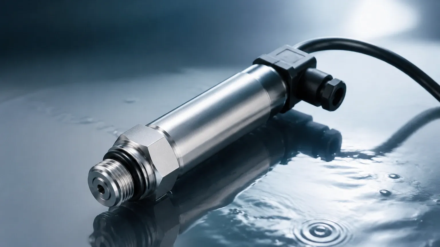
These sensors are designed to be lowered directly into the liquid. They feature a sealed housing, typically made of 316L stainless steel, and a specialized cable that includes a vent tube. This vent tube allows the sensor to compensate for changes in atmospheric pressure, ensuring that the measurement reflects only the liquid height.
* Common Uses: Deep well monitoring, wastewater lift stations, and large reservoir management.
* Key Advantage: Ease of installation in existing tanks or wells without the need for side-wall penetrations.
14-7604be08-989d-4e7d-abf7-87e85d4ea963
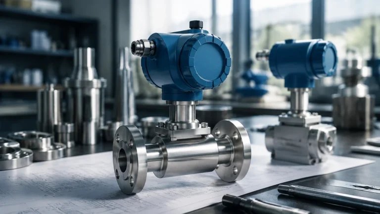
Threaded and Flanged Pressure Transmitters
For closed tanks or hydraulic systems where the sensor must be mounted to the exterior, threaded or flanged transmitters are used. These are installed at the lowest point of the vessel. In pressurized tanks, a differential pressure (DP) transmitter is often required to subtract the top-side gas pressure from the total pressure at the bottom.
* Common Uses: Hydraulic oil reservoirs, chemical storage tanks, and pressurized process vessels.
* Key Advantage: Robustness and ability to handle high process temperatures that might damage submerged electronics.
Practical Selection Table
Choosing the right hydraulic level sensor involves balancing technical requirements with cost-effectiveness. The following table provides a general guideline for technology selection based on common industrial criteria.
| Feature | Submersible Hydrostatic | External Pressure (Threaded) | Ultrasonic (Non-contact) | Radar (Non-contact) |
| :— | :— | :— | :— | :— |
| Measurement Range | Up to 500m (1640 ft) | Up to 100m (328 ft) | 0.3m to 15m (1 to 49 ft) | 0.1m to 70m+ (0.3 to 230 ft) |
| Accuracy | 0.25% to 0.5% FS | 0.1% to 0.5% FS | 0.25% to 0.5% FS | 0.1% FS or better |
| Media Type | Water, Fuel, Thin Oils | Acids, Bases, Oils | Water, Wastewater | Corrosives, Slurries, Solids |
| Temp. Range | -10°C to 70°C | -40°C to 125°C+ | -40°C to 80°C | -40°C to 250°C+ |
| Installation | Top-down (Suspended) | Side or Bottom Mount | Top Mount | Top Mount |
| Atmospheric Venting | Required via cable | Required via housing | Not applicable | Not applicable |
Installation Considerations for Hydraulic Level Sensors
Proper installation is the single most important factor in ensuring the longevity and accuracy of a hydraulic level sensor. Even the highest quality instrument will fail or provide erratic data if environmental factors are ignored.
1. Turbulence and Flow
In tanks with agitators or high-velocity inlet flows, the movement of the liquid can create dynamic pressure errors. For submersible sensors, a stilling well (a perforated pipe) should be used to protect the sensor from physical movement and to dampen the effects of turbulence. For side-mounted sensors, ensure the port is located away from the direct path of incoming fluid.
2. Atmospheric Compensation
For hydrostatic sensors, the back of the sensing diaphragm must be exposed to atmospheric pressure. In submersible models, this is achieved through a capillary tube in the cable. It is vital that this tube is not kinked, blocked, or exposed to moisture. Using a desiccant cartridge at the termination point is a standard industry practice to prevent internal condensation.
3. Cable Protection
In deep-well or outdoor applications, the sensor cable is vulnerable to mechanical damage and environmental degradation. Using a conduit for the cable run and ensuring the cable jacket material (e.g., PUR, PE, or PTFE) is compatible with the measured fluid is essential. For example, a hydraulic level sensor measuring diesel fuel requires a different cable jacket than one measuring potable water.
4. Mounting Location
Avoid mounting sensors in "dead zones" where sediment or sludge can accumulate. If the liquid contains heavy solids, a sensor with a flush diaphragm (rather than a recessed one) should be selected to prevent clogging.
Limitations and Risks
While highly versatile, hydraulic level sensors have specific limitations that engineers must account for during the design phase:
* Density Sensitivity: Since hydrostatic pressure depends on density, any change in the fluid's temperature or concentration that alters its density will result in a measurement error. If the density changes significantly, a temperature-compensated system or a different technology (like radar) may be necessary.
* Overpressure Events: Hydraulic systems can experience sudden pressure spikes. It is critical to select a sensor with an overpressure rating that exceeds the maximum possible surge in the system, not just the maximum operating level.
* Corrosion: In chemical applications, the diaphragm material must be carefully selected. While 316L stainless steel is standard, aggressive media like hydrochloric acid may require Tantalum or Hastelloy diaphragms and specialized gaskets.
Frequently Asked Questions (FAQ)
Q: Can a hydraulic level sensor be used for pressurized tanks?
A: Yes, but a single hydrostatic sensor will measure both the liquid head and the gas pressure above it. To get an accurate level reading in a pressurized vessel, you must use a differential pressure transmitter or two sensors (one at the top and one at the bottom) and calculate the difference.
Q: How often should a submersible level sensor be calibrated?
A: For most industrial applications, an annual calibration check is recommended. However, in harsh environments or applications requiring high precision, semi-annual checks may be necessary. Many Welk sensors offer excellent long-term stability, reducing the frequency of field adjustments.
Q: What is the difference between a pressure transmitter and a level transmitter?
A: Technically, a hydrostatic level transmitter is a pressure transmitter calibrated to output a signal corresponding to a specific depth of a specific liquid. While they use the same sensing technology, level transmitters are often optimized for lower pressure ranges and include features like vented cables.
Q: Does the viscosity of the oil affect the hydraulic level sensor?
A: Viscosity does not affect the hydrostatic pressure at a static level. However, very high viscosity can slow the response time of the sensor if it has a small pressure port. For thick oils or slurries, a flush diaphragm design is preferred.
Conclusion
Selecting a hydraulic level sensor is a task that requires balancing physical principles with practical environmental constraints. Whether you are monitoring a deep groundwater well or a high-pressure hydraulic reservoir, understanding the relationship between pressure and level is the foundation of a successful installation. By considering factors such as media density, turbulence, and atmospheric compensation, engineers can ensure their systems remain accurate and reliable for years to come. For further technical assistance and to explore our full range of measurement solutions, please refer to the resources available on our Main Page.