Carbon Capture and Sequestration Technologies
Carbon Capture and Sequestration Technologies
Carbon capture and sequestration technologies (CCS) represent a critical suite of industrial processes designed to mitigate the impact of greenhouse gas emissions. As global industries strive toward net-zero targets, the implementation of CCS in power generation, cement manufacturing, and chemical processing has transitioned from pilot-scale experiments to large-scale infrastructure projects. Successfully managing these systems requires precise process control, where accurate level measurement of liquids and liquefied gases is essential for both efficiency and safety.
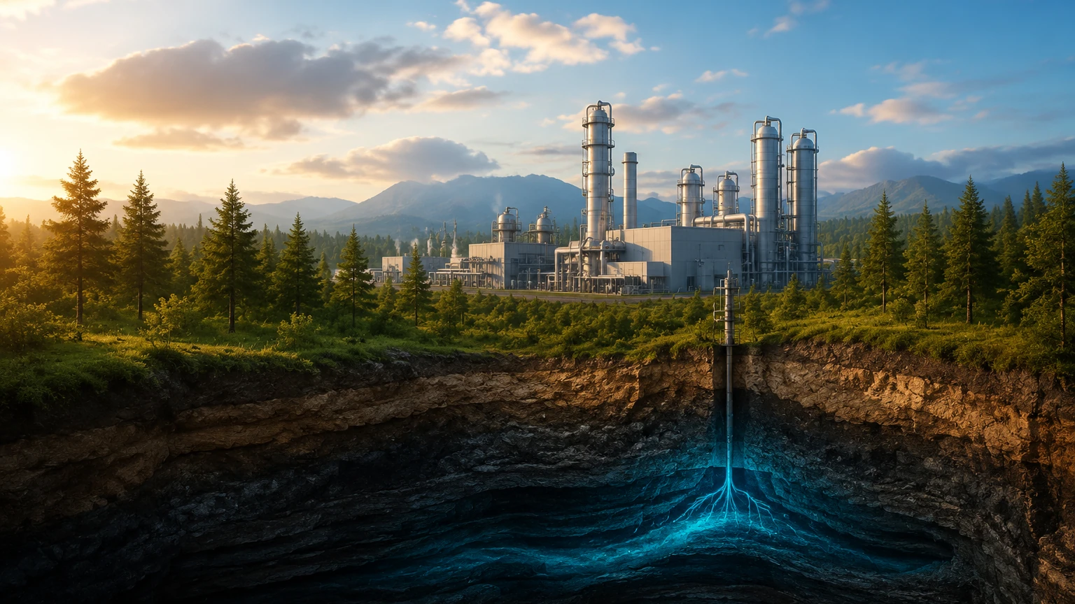
In the context of industrial automation, CCS involves capturing carbon dioxide (CO2) from flue gases or industrial streams, transporting it, and injecting it into deep geological formations for permanent storage. Throughout this lifecycle, instrumentation must withstand challenging conditions, including high pressures, corrosive chemical solvents, and phase changes of the CO2 itself.
Overview of Carbon Capture and Sequestration Technologies
Carbon capture and sequestration technologies are generally categorized by the point in the process where the CO2 is separated. Each method presents unique operating environments for level measurement instruments.
Post-Combustion Capture
This is the most common method for existing power plants. CO2 is removed from the flue gas after the fuel has been burned. The process typically uses chemical absorption, where an amine-based solvent (such as Monoethanolamine or MEA) reacts with the CO2 in an absorber column. The solvent is then heated in a stripper column to release pure CO2 for compression.
Pre-Combustion Capture
Mostly used in gasification processes, the fuel (coal or biomass) is partially oxidized to produce a synthesis gas (syngas) consisting of CO and H2. The CO is reacted with steam to produce CO2 and more H2. The CO2 is then captured before combustion occurs. This process operates at significantly higher pressures than post-combustion capture.
Oxy-Fuel Combustion
In this technology, the fuel is burned in nearly pure oxygen rather than air. This results in a flue gas that is primarily CO2 and water vapor. The water is easily condensed, leaving a high-purity CO2 stream ready for sequestration. This method involves high temperatures and requires robust monitoring of condensate levels.
Measurement Principles in CCS Processes
Before selecting instrumentation for CCS applications, it is vital to understand the physics of the measurement principles employed. In carbon capture and sequestration technologies, the media often transition between gas, liquid, and supercritical states.
Time-of-Flight (ToF) Principles
Radar and ultrasonic sensors utilize the Time-of-Flight principle. A signal is emitted from the sensor, travels to the surface of the medium, and reflects back. The distance is calculated based on the speed of the signal.
- Radar: Uses electromagnetic waves. These are largely unaffected by pressure and temperature changes, making them ideal for high-pressure CO2 storage.
- Ultrasonic: Uses sound waves. Since the speed of sound varies with gas density and temperature, these are better suited for atmospheric water treatment tanks within the CCS facility rather than high-pressure vessels.
Hydrostatic Pressure
This principle relies on the relationship between the height of a liquid column and the pressure it exerts at the base ($P = \rho gh$). In CCS, hydrostatic transmitters are often used in solvent storage tanks. However, because CO2 density changes significantly with pressure and temperature, compensation is required for accurate level readings in CO2 transport vessels.
Magnetic Displacement
Magnetic level gauges utilize a float containing a magnet that moves with the liquid level inside a bypass chamber. As the float moves, it flips magnetic flags or interacts with a reed switch/transmitter. This provides a clear visual indication and a secondary electronic signal without direct contact between the electronics and the process medium.
Level Measurement Technologies for Capture and Storage
Selecting the right instrument depends on the specific stage of the CCS process. Engineers must evaluate chemical compatibility, pressure ratings, and the potential for foam or vapor.
Radar Level Meters
Radar technology is the gold standard for many carbon capture and sequestration technologies. For amine absorbers, guided wave radar (GWR) is often preferred because the probe guides the signal through the foam that frequently forms on the surface of the solvent. Non-contact radar is excellent for large CO2 storage spheres where the internal environment is highly pressurized (up to 100 bar or 1450 psi).
Ultrasonic Level Sensors
In the peripheral systems of a CCS plant, such as cooling water loops or wastewater treatment for the capture unit, ultrasonic sensors offer a cost-effective, non-contact solution. They are limited to applications where the vapor space is stable and the pressure is near atmospheric.
Magnetic Level Gauges
Magnetic gauges are highly valued in CO2 liquefaction plants. Because CO2 is often stored at low temperatures (-20°C to -50°C / -4°F to -58°F), these gauges can be equipped with vacuum jackets to prevent ice buildup on the indicator, ensuring the level remains visible to operators.
Level Switches
Redundancy is critical in CCS to prevent overfilling of high-pressure tanks. Tuning fork or float-type level switches act as independent high-level alarms (HLA) to trigger emergency shutdowns (ESD) if primary transmitters fail.
Technical Selection Criteria and Comparison
When designing a system for carbon capture and sequestration technologies, the following table provides a general guideline for instrument selection based on typical process conditions:
| Process Stage | Typical Medium | Pressure/Temp | Recommended Technology | Why? |
| :— | :— | :— | :— | :— |
| Amine Absorber | Amine Solvent | Low P / Mid T | Guided Wave Radar | Resists foam interference. |
| CO2 Stripper | Solvent/CO2 | Mid P / High T | Radar or Hydrostatic | Handles high temperatures well. |
| CO2 Buffer Tank | Liquefied CO2 | High P / Low T | Magnetic Level Gauge | Visual safety and low-temp options. |
| Storage Wellhead | Supercritical CO2 | Very High P | Non-contact Radar | No moving parts; resists high P. |
| Water Treatment | Process Water | Atmospheric | Ultrasonic | Cost-effective and reliable. |
For more detailed technical specifications on these instruments, engineers should Review product options and application support to ensure compliance with specific project safety standards.
Installation Considerations for High-Pressure CO2 Systems
In CCS applications, the physical installation of the sensor is as important as the technology itself. CO2 is a small molecule that can permeate many sealing materials, leading to instrument failure or leaks.
1. Sealing and Gaskets: For high-pressure CO2, use metallic seals or specialized elastomers like FFKM (Perfluoroelastomer) to prevent explosive decompression. Standard EPDM or Nitrile seals may fail when the system is depressurized.
2. Stilling Wells and Bypass Chambers: In turbulent vessels or those where foaming occurs (like capture columns), installing a radar sensor inside a stilling well or using a bypass chamber can stabilize the surface and improve signal-to-noise ratios.
3. Nozzle Height and Diameter: For non-contact radar, ensure the nozzle is short enough to prevent signal interference from the nozzle walls. The diameter should be sufficient to allow the radar beam to clear internal obstructions like heating coils or ladders.
4. Orientation: Level switches should be installed horizontally for point detection, while continuous transmitters are mounted at the top of the vessel. Ensure there is no direct flow of liquid onto the sensor face, which could cause false readings.
Operational Limitations and Troubleshooting
Despite the robustness of modern carbon capture and sequestration technologies, certain operational factors can impact measurement accuracy.
* Dielectric Constant ($ε_r$): Radar depends on the dielectric constant of the medium. Liquid CO2 has a low dielectric constant ($ε_r ≈ 1.6$), which results in a weak reflection. High-sensitivity radar modules or Guided Wave Radar with coaxial probes are necessary for reliable tracking.
* Vapor Phase Density: At high pressures, the density of the gas in the vapor space increases. This can slow down the speed of radar or ultrasonic waves. Modern radar transmitters include gas phase compensation features to correct for this error automatically.
* Foaming: Amine-based capture systems are prone to foaming. If the foam is thick and dense, it may be detected as the liquid level by ultrasonic sensors. Radar, particularly GWR, is better at "seeing through" light foam to the true liquid interface.
Frequently Asked Questions (FAQs)
Q: Can I use a standard ultrasonic sensor for liquefied CO2 storage?
A: Generally, no. Liquefied CO2 is stored under pressure. The change in the gas composition and pressure in the vapor space significantly alters the speed of sound, leading to massive inaccuracies. Radar or hydrostatic sensors are much more reliable for this application.
Q: How does temperature affect level measurement in carbon capture?
A: In capture stages like the stripper, temperatures can exceed 120°C (248°F). This can affect the electronics of the sensor. It is recommended to use remote-mounted electronics or cooling fins (heat dissipators) to protect the transmitter head.
Q: What is the best way to handle the low dielectric constant of CO2?
A: Using a Guided Wave Radar (GWR) with a coaxial probe is the most effective method. The probe concentrates the radar energy, allowing the sensor to detect the weak reflection from the low-dielectric CO2 surface more accurately than a non-contact horn antenna.
Conclusion
The successful deployment of carbon capture and sequestration technologies hinges on precise process monitoring. By understanding the measurement principles of radar, ultrasonic, and hydrostatic technologies, engineers can select the most appropriate instrumentation for the rigorous demands of CO2 capture and storage. Proper installation, combined with an awareness of the unique physical properties of CO2 and chemical solvents, ensures long-term reliability and safety in these vital industrial environmental projects.
Download Carbon Capture and Sequestration Technologies as a PDF