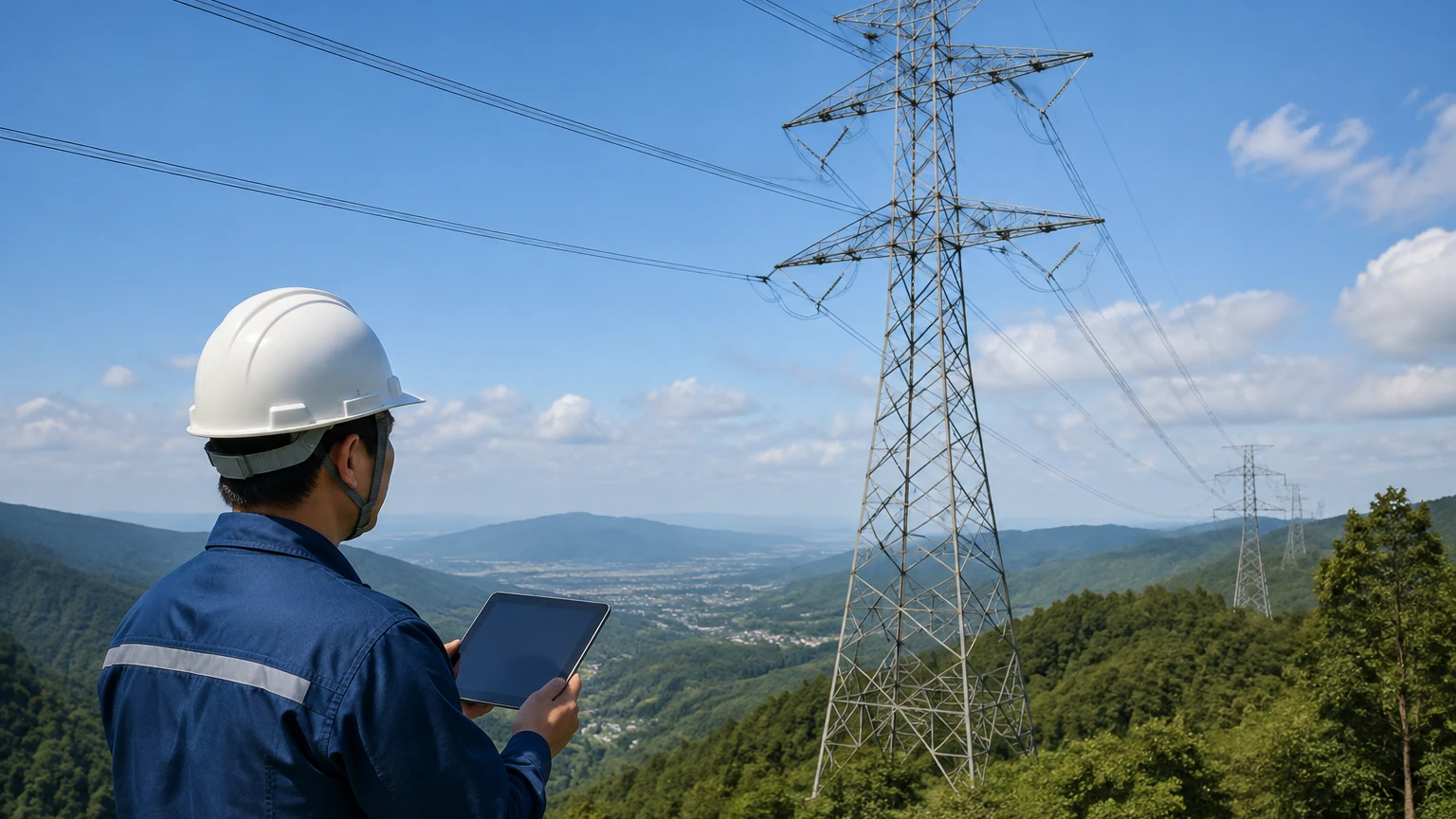
Power Line Monitoring Equipment
Power Line Monitoring Equipment
In the landscape of industrial automation and process control, the reliability of power infrastructure is as critical as the accuracy of the sensors it supports. Power line monitoring equipment serves as the diagnostic backbone for electrical distribution networks, ensuring that facilities—ranging from water treatment plants to oil refineries—maintain continuous operation. For engineers managing complex installations of radar level meters or ultrasonic sensors, understanding the health of the power lines feeding these instruments is essential for preventing data corruption, equipment damage, and unplanned downtime.
Measurement Principles of Power Line Monitoring
Power line monitoring equipment utilizes several physical and electrical principles to assess the state of conductors and the quality of the electricity they carry. These systems are designed to monitor both the electrical parameters (voltage, current, frequency) and the physical condition of the lines (temperature, sag, vibration).
1. Current and Voltage Sensing
Most monitoring devices employ Current Transformers (CTs) or Rogowski coils to measure amperage. CTs work on the principle of electromagnetic induction, producing a secondary current proportional to the primary current. Rogowski coils, which are air-cored toroidal coils, are often preferred for retrofitting because they are flexible and do not saturate at high currents. Voltage is typically measured using Potential Transformers (PTs) or capacitive voltage dividers, which step down high voltages to measurable levels for digital processing.
2. Thermal Monitoring
The ampacity—or maximum current capacity—of a power line is largely limited by temperature. Power line monitoring equipment often uses contact-based thermistors or non-contact infrared (IR) sensors to track conductor temperature. Advanced systems may use the heat balance equation, factoring in ambient temperature, wind speed, and solar radiation to calculate the "Dynamic Line Rating" (DLR), allowing for higher throughput during cooler conditions.
3. Mechanical Sag and Tension
Physical monitoring involves measuring the sag of overhead lines. This is often achieved through high-precision accelerometers that detect the vibration frequency of the span, or through GPS-based units that track the precise coordinates of the conductor's lowest point. In industrial plant environments, tension-monitoring load cells integrated into dead-end insulators provide real-time data on mechanical stress caused by ice loading or thermal expansion.
Integration with Industrial Level Measurement
For manufacturers like Welk, providing reliable level measurement solutions requires a stable electrical environment. Power line monitoring equipment plays a vital role in the ecosystem where level sensors operate. Industrial level transmitters, such as hydrostatic transmitters or magnetic level gauges, are sensitive to power quality issues like voltage sags, surges, and harmonic distortion.
When power line monitoring equipment detects a transient voltage surge, it can trigger protective relays or alert operators to check the calibration of sensitive field instruments. Furthermore, in remote water treatment or oil and gas applications, where sensors are powered by long-distance distribution lines, monitoring the power line ensures that the Main Page of the facility’s SCADA system receives accurate, noise-free data from the level meters.
Selection Criteria for Power Line Monitoring Systems
Choosing the right monitoring equipment requires a balance between technical requirements and environmental constraints. Engineers should evaluate the following criteria:
| Feature | Description | Importance for Industrial Facilities |
| :— | :— | :— |
| Measurement Accuracy | Precision of current (typically ±1%) and temperature (±2°C). | Critical for calculating true ampacity and preventing conductor damage. |
| Communication Protocol | Support for Modbus, DNP3, or IEC 61850. | Ensures seamless integration with existing plant PLC and SCADA systems. |
| Power Source | Battery, solar, or inductive energy harvesting from the line. | Determines maintenance intervals, especially in hard-to-reach locations. |
| Data Sampling Rate | Frequency of measurements (e.g., 1 sample/second to 128 samples/cycle). | High rates are necessary for detecting fast transients and faults. |
| Environmental Rating | IP67 or NEMA 4X protection against dust and moisture. | Essential for chemical plants and outdoor water treatment facilities. |
Installation Considerations and Best Practices
Proper installation is paramount to ensure both the safety of personnel and the accuracy of the data collected by power line monitoring equipment.
1. Sensor Placement: Sensors should be placed at "critical spans"—areas where the line is most likely to experience high temperatures or where physical clearance is minimal (e.g., over a roadway or near a metal tank).
2. Grounding and Isolation: In high-voltage environments, ensuring proper galvanic isolation between the monitoring equipment and the data acquisition system is vital. Optical fiber is frequently used for signal transmission to eliminate electromagnetic interference (EMI).
3. Safety Clearances: Installation often requires "hot-stick" methods or de-energizing the line. Personnel must maintain Minimum Approach Distances (MAD) as defined by local safety standards (e.g., OSHA or IEC).
4. Calibration: Before commissioning, sensors must be calibrated against a known standard. For industrial level measurement applications, it is also recommended to verify that the power monitoring system does not introduce high-frequency noise into the instrument loops.
Limitations and Common Risks
While power line monitoring equipment is highly effective, it is not without limitations. Engineers must account for the following risks:
* Electromagnetic Interference (EMI): High-voltage lines generate intense electromagnetic fields that can interfere with wireless communication modules within the monitoring device. Shielding and robust error-correction protocols are necessary.
* Energy Harvesting Thresholds: Many line-powered monitors require a minimum current (often 5A to 10A) to flow through the conductor to power the electronics. During low-load periods, these devices may go offline unless equipped with backup batteries.
* Extreme Weather: While designed for outdoor use, extreme ice buildup or hurricane-force winds can physically displace or damage sensors. Regular physical inspections are required alongside digital monitoring.
* Data Overload: High-frequency sampling can generate massive amounts of data. Without an intelligent edge-computing layer to filter out noise, the SCADA system may become overwhelmed with non-critical alerts.
Frequently Asked Questions (FAQ)
Q: Can power line monitoring equipment detect faults before they happen?
A: Yes, through "predictive monitoring." By tracking partial discharge (PD) or identifying unusual harmonic patterns, the equipment can signal that an insulator is failing or a transformer is overheating before a full-scale fault occurs.
Q: How does line monitoring improve the lifespan of level sensors?
A: By monitoring for over-voltage conditions and ensuring a stable power supply, the equipment prevents the internal electronics of level transmitters from being subjected to thermal stress and voltage spikes, which are leading causes of premature sensor failure.
Q: Is it possible to monitor underground power cables?
A: Yes, though the technology differs. Underground monitoring typically involves Distributed Temperature Sensing (DTS) using fiber optic cables laid alongside the power lines to detect "hot spots" caused by insulation breakdown.
Q: What is the typical maintenance schedule for these devices?
A: Most modern solid-state monitors require minimal maintenance. However, batteries (if used) generally need replacement every 3 to 5 years, and sensors should be checked for physical debris or corrosion annually.
Conclusion
For industrial operations, power line monitoring equipment is more than just a safety tool; it is a fundamental component of asset management. By providing real-time visibility into the health of the electrical distribution network, these systems ensure that critical instrumentation—including the radar and ultrasonic level meters produced by Welk—can perform their functions without interference.
When designing a new facility or upgrading an existing process line, engineers should prioritize the integration of robust power monitoring to safeguard their investment in automation. For more information on selecting the right measurement instruments and ensuring their optimal performance within your power infrastructure, please visit our Main Page to explore our full range of industrial solutions.