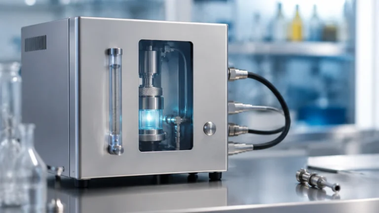
In Line Ph Probe
In Line Ph Probe
In industrial process control, the continuous monitoring of liquid acidity or alkalinity is fundamental to ensuring product quality, equipment longevity, and environmental compliance. An in line pH probe is a specialized electrochemical sensor designed for direct installation into process piping, tanks, or reactors. Unlike laboratory-based sampling, in-line measurement provides real-time data, allowing automated control systems to respond instantly to chemical fluctuations.
For engineers and plant managers, selecting the correct in line pH probe requires a deep understanding of electrochemical principles, material science, and the specific hydraulic conditions of the process. This guide explores the technical foundations of pH measurement, selection criteria for industrial environments, and the critical role these sensors play alongside other instrumentation, such as level measurement systems found on the Main Page.
Measurement Principles of In Line pH Probes
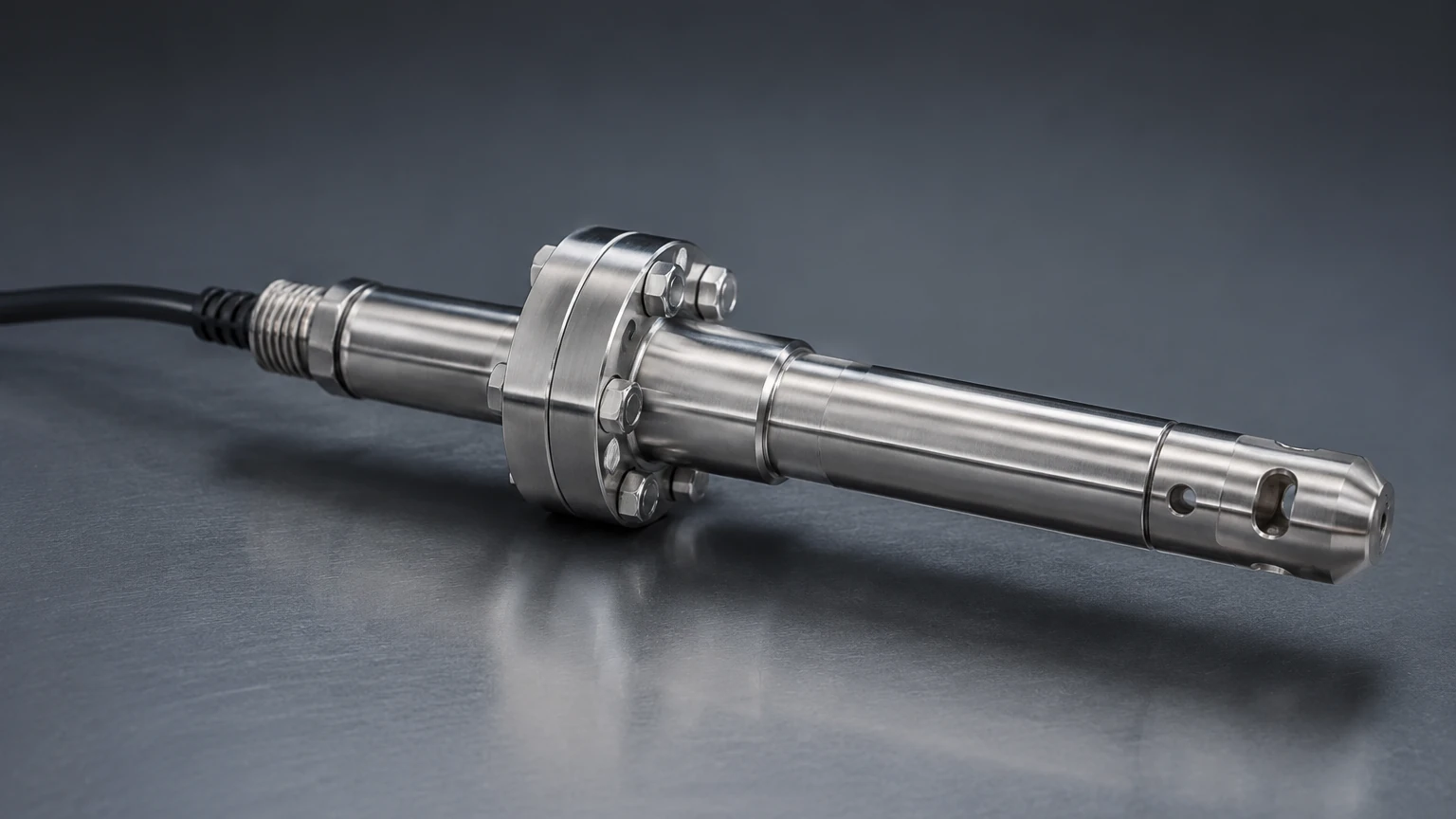
The measurement of pH is based on the potentiometric method, which determines the activity of hydrogen ions in a solution. An industrial in line pH probe typically functions as a galvanic cell consisting of two primary components: a sensing electrode and a reference electrode.
The Sensing Electrode
The sensing electrode features a specialized pH-sensitive glass membrane. When this membrane comes into contact with an aqueous solution, a hydrated layer (gel layer) forms on both the inner and outer surfaces. Hydrogen ions in the process fluid exchange with ions in the glass membrane, creating a potential difference. This potential is proportional to the concentration of hydrogen ions in the solution, governed by the Nernst Equation.
The Reference Electrode
The reference electrode provides a stable, known potential against which the sensing electrode's potential is measured. It typically consists of a silver/silver chloride (Ag/AgCl) element immersed in a concentrated potassium chloride (KCl) electrolyte. To maintain electrical continuity with the process fluid, the reference electrode uses a "junction"—a porous plug made of ceramic, Teflon (PTFE), or wood—that allows a controlled flow of electrolyte into the medium.
Temperature Compensation
pH measurement is highly temperature-dependent. Temperature affects both the chemical activity of the ions and the sensitivity of the glass electrode (the Nernstian slope). Consequently, most modern in line pH probes incorporate an internal temperature element, such as a PT100 or PT1000 resistance temperature detector (RTD), to provide Automatic Temperature Compensation (ATC).
Technical Selection Criteria
Choosing an in line pH probe is not a one-size-fits-all process. Industrial environments present challenges such as high pressure, extreme temperatures, and aggressive chemicals that can quickly degrade standard sensors.
1. Temperature and Pressure Ratings
Standard glass electrodes are sensitive to thermal shock and mechanical stress. In pressurized pipelines, the probe must be rated for the maximum operating pressure (often up to 10 bar or 145 psi). Similarly, high-temperature applications (above 80°C) require specialized glass formulations and high-temperature electrolytes to prevent the reference system from boiling or the glass from dissolving.
2. Reference Junction Type
The junction is often the "weak link" in a pH probe. In dirty or oily processes, a standard porous ceramic junction can become clogged, leading to measurement drift and slow response times.
- Teflon (PTFE) Junctions: Ideal for processes with suspended solids or oils.
- Open Junctions (Solid Polymer): Used in very harsh, clogging media where no traditional junction can survive.
- Ceramic Junctions: Suitable for clean water and general chemical applications.
3. Electrolyte Configuration
- Gel-filled: Maintenance-free and suitable for most general applications, though they cannot be refilled.
- Liquid-filled: Allows for the replenishment of electrolyte, extending the probe's life in demanding environments, but requires a pressurized reservoir to ensure electrolyte flow into the process.
4. Body Materials
The outer body of the probe must be chemically compatible with the process fluid. Common materials include:
- Glass: Standard for most chemical applications.
- PVDF (Kynar): Excellent chemical resistance for corrosive environments.
- 316L Stainless Steel: Used in sanitary applications (food, beverage, and pharma) for mechanical durability.
Practical Selection Table
| Application Type | Recommended Junction | Body Material | Temperature Range |
| :— | :— | :— | :— |
| General Water Treatment | Porous Ceramic | Glass / Plastic | 0°C to 80°C |
| Wastewater (High Solids) | Porous PTFE | PVDF | -5°C to 100°C |
| Chemical Processing (Corrosive) | Solid Polymer | Glass | -10°C to 130°C |
| Food & Beverage (Sanitary) | Ceramic / Liquid | 316L Stainless Steel | 0°C to 135°C (CIP) |
| Pure Water / Condensate | Liquid-filled | Glass | 0°C to 60°C |
Installation Considerations and Best Practices
The physical placement of an in line pH probe significantly impacts its accuracy and lifespan. Proper engineering during the installation phase prevents common failure modes.
Mounting Orientation
pH probes should never be installed horizontally or upside down. The internal electrolyte must stay in contact with the glass bulb. A minimum angle of 15° above the horizontal is required to ensure that air bubbles within the probe do not interrupt the internal electrical circuit.
Flow Velocity and Turbulence
While some flow is necessary to ensure a representative sample, excessive velocity (above 2 m/s) can cause "streaming potentials" or physical erosion of the glass membrane. Conversely, stagnant flow can lead to fouling. Probes are often installed in a bypass loop or a dedicated flow cell to control the environment around the sensor.
Grounding and Electrical Interference
pH signals are high-impedance millivolt signals, making them extremely susceptible to electrical noise from pumps, motors, and variable frequency drives (VFDs). Using shielded cables and ensuring the process piping is properly grounded (or using a solution ground/matching electrode) is essential for stable readings.
Retractable Assemblies
In processes that cannot be easily shut down, retractable probe holders (manual or pneumatic) allow the sensor to be removed for cleaning and calibration without stopping the flow. This is critical for 24/7 operations in the chemical and oil and gas sectors.
Limitations and Common Risks
Despite their sophistication, in line pH probes are consumable items with a finite lifespan. Users must be aware of the following risks:
1. Dehydration: If the process line is drained and the probe is left dry, the hydrated gel layer on the glass membrane will collapse. This can cause permanent damage or require extensive rehydration.
2. Chemical Attack: Hydrofluoric acid (HF) specifically attacks glass. In applications containing HF, specialized non-glass (ISFET) sensors or HF-resistant glass must be used.
3. Fouling and Scaling: Calcium carbonate scale, oils, or biological growth can coat the sensor. This insulates the glass membrane from the hydrogen ions, leading to sluggish response times and inaccurate data.
4. Reference Poisoning: Certain chemicals, such as sulfides, cyanides, and heavy metals, can react with the silver ions in the reference electrolyte, forming precipitates that clog the junction.
Maintenance and Calibration Protocols
Regular maintenance is the only way to ensure the reliability of an in line pH probe. Most industrial protocols involve:
- Cleaning: Using dilute acids (for scale), detergents (for oils), or pepsin (for proteins) to restore the glass membrane's sensitivity.
- Two-Point Calibration: Using standardized buffer solutions (typically pH 4.01, 7.00, or 10.01). The "offset" is determined at pH 7, and the "slope" is determined using a second buffer. A slope below 85% of the theoretical Nernstian value (59.16 mV/pH at 25°C) usually indicates the probe needs replacement.
- Verification: Periodically comparing the in-line reading with a calibrated portable meter or laboratory sample.
Integration with Industrial Automation
In modern industrial plants, pH measurement is rarely an isolated data point. It is integrated into a broader automation strategy that includes level, flow, and pressure monitoring. For instance, in a wastewater neutralization tank, an ultrasonic or radar level meter (available through the Main Page) ensures the tank does not overflow while the in line pH probe controls the dosing pumps for acid or caustic reagents.
By synchronizing level data with pH data, operators can calculate the volume of reagent required for neutralization more accurately, reducing chemical waste and improving process efficiency. This holistic approach to instrumentation is a hallmark of advanced industrial automation.
Frequently Asked Questions (FAQs)
Q: How long does an in line pH probe typically last?
A: In clean water applications, a probe may last 12 to 24 months. In harsh chemical processes or high-temperature environments, the lifespan may be reduced to 3 to 6 months.
Q: Can I use a standard lab pH probe in a pipe?
A: No. Laboratory probes are not designed to withstand the pressure, flow, or mechanical vibrations of a process line. They lack the necessary mounting threads and pressure-resistant seals.
Q: What is the difference between a pH probe and a pH sensor?
A: In industrial terms, the "probe" or "sensor" refers to the electrochemical element. The "transmitter" or "analyzer" is the electronic device that interprets the millivolt signal and converts it into a 4-20mA or digital output (like Modbus or HART).
Q: How often should I calibrate my in line pH probe?
A: This depends on the process. In stable, clean environments, once a month may suffice. In aggressive or high-accuracy applications, weekly or even daily calibration checks may be required.
Conclusion
The in line pH probe is a vital instrument for maintaining chemical balance in industrial processes. While the underlying electrochemical principle is well-established, the success of the measurement depends on matching the sensor's materials and design to the specific rigors of the application. By considering factors such as junction type, body material, and installation geometry, and by integrating these sensors with reliable level measurement solutions, engineers can achieve robust and accurate process control.