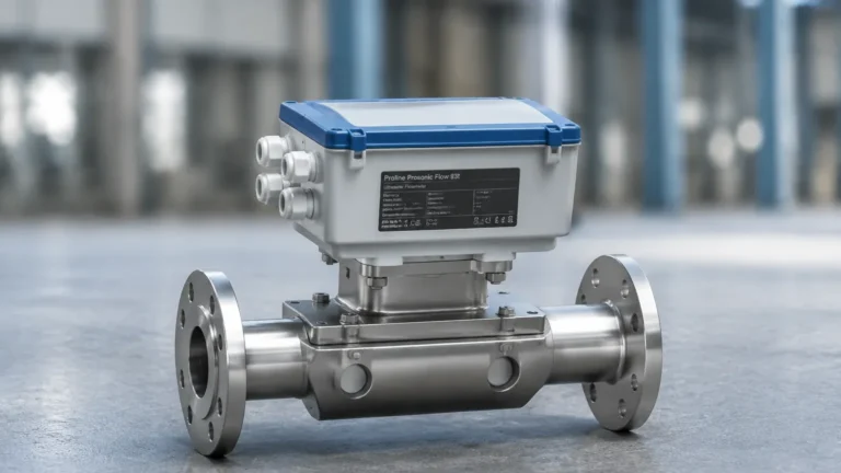
Pmc131
Pmc131
In the field of industrial process control, the accurate measurement of liquid levels is a fundamental requirement for safety, efficiency, and inventory management. Among the various technologies available, hydrostatic pressure measurement remains one of the most reliable and widely adopted methods. The pmc131 is a specific model of pressure transmitter that has become a benchmark for compact, cost-effective level and pressure sensing in various industries. This article provides a comprehensive technical overview of the pmc131 technology, the principles of hydrostatic measurement, and practical guidance for engineering selection and installation.
Measurement Principles of Hydrostatic Pressure
Before evaluating specific hardware like the pmc131, it is essential to understand the physical principles that govern its operation. Hydrostatic level measurement is based on the relationship between the height of a liquid column and the pressure exerted at the base of that column. This is defined by the hydrostatic paradox, expressed by the formula:
P = ρ · g · h
Where:
* P is the hydrostatic pressure (Pa or bar).
* ρ (rho) is the density of the medium (kg/m³).
* g is the local acceleration due to gravity (approximately 9.81 m/s²).
* h is the height of the liquid (m).
In a vented tank (open to the atmosphere), the transmitter measures the gauge pressure. Since gravity is constant and the density of the liquid is usually known, the pressure measured by the sensor is directly proportional to the level of the liquid. The pmc131 utilizes a dry ceramic sensor cell to detect this pressure. Unlike metallic diaphragms that use a fill fluid (such as silicone oil) to transmit pressure to the sensing element, a dry ceramic sensor interacts directly with the process medium or via a thin protective layer.
When pressure is applied to the ceramic diaphragm, it deflects slightly (typically less than 0.01 mm). This deflection changes the capacitance between the diaphragm and a substrate, or in some designs, alters the resistance of a strain gauge bridge. The internal electronics of the pmc131 convert this physical change into a standardized industrial signal, typically a 4 to 20 mA analog output.
Technical Overview of the PMC131 Transmitter
The pmc131 is designed as a compact, entry-level pressure transmitter intended for applications where space is limited and high-end features like integrated displays or complex digital protocols are not required. It is frequently used in water treatment, food and beverage processing, and general industrial automation.
Key Design Features
1. Ceramic Sensor Technology: The heart of the unit is a high-purity ceramic (99.9% Al2O3) sensor. Ceramic is exceptionally hard and chemically inert, making it resistant to abrasion and many corrosive substances that would damage stainless steel diaphragms.
2. Overload Resistance: One of the primary advantages of ceramic cells is their high overload capability. The pmc131 can often withstand pressures many times its rated range without permanent deformation or calibration shift.
3. Compact Form Factor: With its small footprint and standard process connections (such as G1/2" or NPT threads), it can be installed in tight pipework or small tank nozzles where larger transmitters would not fit.
4. Environmental Protection: These units are typically rated to IP65 or higher, ensuring reliability in wash-down environments or outdoor installations.
For engineers seeking a broader range of industrial level measurement solutions, including radar and ultrasonic alternatives, visiting the Main Page provides a comprehensive resource for comparing different sensing technologies.
Selection Criteria and Comparative Analysis
Choosing the correct transmitter requires a detailed analysis of the process conditions. While the pmc131 is versatile, it must be matched to the specific requirements of the application. The following table outlines the typical selection criteria for hydrostatic transmitters in this class.
Selection Table: Hydrostatic Transmitter Evaluation
| Feature | Specification / Requirement | Engineering Consideration |
| :— | :— | :— |
| Measuring Range | 0.1 bar to 40 bar (1.5 psi to 600 psi) | Ensure the range covers the maximum possible tank height plus a safety margin. |
| Accuracy | Typically 0.5% of Full Scale | Sufficient for most process control; high-precision custody transfer may require 0.1%. |
| Wetted Materials | Ceramic (Al2O3), 316L SS, FKM/EPDM seals | Check chemical compatibility with the process fluid (e.g., acids, bases, oils). |
| Process Temperature | -20°C to +100°C (-4°F to 212°F) | High-temperature applications may require remote seals or cooling fins. |
| Output Signal | 4-20 mA (2-wire) | Standard signal compatible with most PLCs and DCS systems. |
| Process Connection | Threaded (G1/2, NPT 1/2) | Must match existing tank nozzles or pipe fittings. |
When selecting a transmitter, engineers must also consider the "Turndown Ratio," which is the ratio between the maximum and minimum calibrated span. While the pmc131 has a fixed or limited adjustment range, higher-end models from manufacturers like Welk offer greater flexibility for multi-purpose use.
Engineering Guidelines for Installation
Proper installation is critical to the longevity and accuracy of a hydrostatic level sensor. Even the most robust pmc131 unit can fail or provide erroneous readings if installed incorrectly.
Mounting Position
The transmitter should ideally be installed at the lowest point of the tank. If the sensor is mounted on a side wall, any liquid below the level of the diaphragm will not be measured (this is known as the "zero offset"). In such cases, the PLC must be programmed to account for the unmeasured volume at the bottom of the tank.
Pressure Compensation
For gauge pressure measurement in vented tanks, the back of the sensor diaphragm must be referenced to atmospheric pressure. The pmc131 achieves this through a small vent in the housing or via a vented cable. It is vital to ensure this vent is not blocked by paint, dust, or moisture. If moisture enters the vent, it can cause internal corrosion or lead to measurement errors due to air pressure fluctuations.
Avoiding Turbulence and Sludge
* Turbulence: If the tank has an agitator or a high-velocity inlet, the resulting turbulence can cause pressure spikes and "noisy" readings. In these scenarios, the sensor should be installed in a stilling well (a bypass pipe) to dampen the fluid movement.
* Sedimentation: In applications involving wastewater or slurries, solids may settle at the bottom of the tank and coat the sensor diaphragm. The pmc131 should be mounted slightly above the very bottom to avoid being buried in sludge, or a flush-mounted diaphragm should be used to prevent buildup.
Electrical Connection
Use shielded cables to protect the 4-20 mA signal from electromagnetic interference (EMI), especially if the cable runs near high-voltage motors or frequency inverters. Ensure the cable entry is sealed correctly to maintain the IP rating of the device.

Operational Limitations and Risk Mitigation
While the pmc131 is a robust instrument, it is not a universal solution. Engineers must be aware of its limitations to avoid premature failure.
1. Vacuum Applications: Ceramic sensors are excellent for positive pressure, but some designs are sensitive to vacuum. If a tank is under vacuum, the diaphragm may be pulled away from its support, potentially causing damage or loss of calibration. Always verify the vacuum rating if the process involves negative pressures.
2. Temperature Shocks: Rapid changes in process temperature (e.g., during a CIP or Clean-In-Place cycle in food production) can cause thermal shock. While ceramic is heat-resistant, the expansion rates of the ceramic cell and the metal housing differ. This can lead to temporary measurement errors or seal failure if the shocks are frequent and extreme.
3. Density Fluctuations: Since hydrostatic measurement relies on density (ρ), any change in the liquid's density will lead to a linear error in level measurement. If a tank is used for different liquids or if the temperature causes significant density changes, the system must be compensated using a secondary temperature sensor or a differential pressure setup.
4. Physical Damage: Although ceramic is hard, it is brittle. Dropping the transmitter or hitting the diaphragm with a sharp tool during cleaning will shatter the ceramic cell.
Maintenance and Lifecycle Management
Hydrostatic transmitters like the pmc131 are generally low-maintenance because they have no moving parts. However, a routine maintenance schedule is recommended to ensure long-term reliability.
* Visual Inspection: Periodically check the transmitter for signs of corrosion on the housing or leaks at the process connection. Inspect the cable for cracks or signs of UV degradation.
* Zero-Point Check: Over time, sensors may experience a slight "zero drift." When the tank is empty, verify that the transmitter outputs exactly 4.00 mA. Many modern systems allow for a digital zero-adjustment to recalibrate the baseline.
* Cleaning: If the medium is prone to scaling or coating, the diaphragm should be cleaned. Use a soft cloth and a compatible solvent. Never use a wire brush or a screwdriver to scrape the diaphragm, as this will destroy the sensor.
For facilities managing a large fleet of instruments, standardizing on a reliable manufacturer like Welk can simplify spare parts inventory and training. Detailed technical specifications for various industrial models can be found on the Main Page.
Frequently Asked Questions
Q: Can the pmc131 be used for pressurized tanks?
A: No, the pmc131 is a gauge pressure transmitter. In a pressurized (closed) tank, the sensor would measure the sum of the liquid's hydrostatic pressure and the gas pressure above it. For closed tanks, a differential pressure (DP) transmitter is required to subtract the top pressure from the bottom pressure.
Q: What is the difference between a ceramic sensor and a metallic sensor?
A: Ceramic sensors are "dry," meaning they don't use fill oil. They are more resistant to abrasion and chemical attack but can be brittle. Metallic sensors use a thin diaphragm and oil to transmit pressure; they are better for high-temperature or high-pressure applications but are more easily scratched or dented.
Q: How do I calculate the mA output for a specific level?
A: Use the linear scaling formula:
*Output (mA) = 4 + [ (Current Level / Max Level) * 16 ]*.
For example, if a 5-meter tank is at 2.5 meters, the output would be 4 + [ (2.5/5) * 16 ] = 12 mA.
Q: Is the pmc131 suitable for hygienic applications?
A: It depends on the specific variant. While the ceramic material is safe, the process connection must meet local hygienic standards (like 3-A or EHEDG) to ensure there are no dead spaces where bacteria can grow. Specific hygienic models with flush diaphragms are usually preferred for dairy and pharmaceutical use.
By understanding these technical nuances, engineers can effectively integrate the pmc131 or similar hydrostatic transmitters into their process architectures, ensuring accurate level monitoring and long-term operational stability.