Stream Velocity Meter
Stream Velocity Meter
In industrial water management, environmental monitoring, and civil engineering, the accurate measurement of water movement is critical for process control and safety. A stream velocity meter is a specialized instrument designed to quantify the speed at which water flows through a specific cross-section of a channel, river, or pipe. While level measurement provides the vertical dimension of a water body, velocity measurement adds the temporal and directional component necessary to calculate total discharge and monitor hydraulic dynamics.
For professionals managing water treatment facilities or industrial automation systems, understanding the nuances of velocity measurement is as essential as monitoring tank levels. This guide examines the fundamental principles, technological variations, and practical application criteria for selecting the appropriate stream velocity meter for industrial and environmental contexts.
Measurement Principles of Stream Velocity Meters
To select the right instrument, engineers must first understand the physics behind different measurement methods. Each principle has specific strengths depending on the water's clarity, the presence of suspended solids, and the accessibility of the stream.
Radar (Non-Contact Doppler)
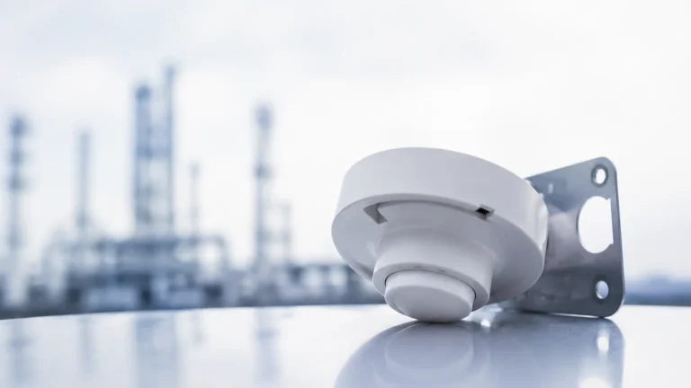
Radar-based stream velocity meters utilize the Doppler effect. The sensor emits a microwave signal at a known frequency toward the water surface. As the signal hits moving surface ripples or waves, it is reflected back to the sensor with a frequency shift proportional to the surface velocity.
* Advantages: Because the sensor is mounted above the water, it is immune to fouling, debris damage, and corrosion. It is ideal for high-velocity streams or flooding conditions where submerged sensors might be swept away.
* Limitations: It measures surface velocity only. To determine the mean velocity of the entire water column, a conversion factor (typically between 0.85 and 0.90) is applied based on the channel's hydraulic characteristics.
Ultrasonic Doppler (Submerged)
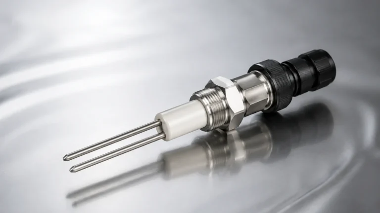
Submerged ultrasonic sensors also use the Doppler shift but operate within the water column. These meters emit high-frequency sound waves that bounce off suspended particles, sediment, or small air bubbles moving with the flow. The frequency change of the returning echoes determines the velocity at the sensor's depth.
* Advantages: These sensors can provide a more direct measurement of the velocity within the water column rather than just the surface.
* Limitations: They require a minimum concentration of "scatterers" (particles or bubbles) to function. In extremely pure water, the signal may not return. Additionally, as submerged devices, they are prone to biofouling and physical obstruction.
Electromagnetic Induction
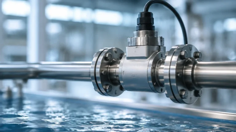
Based on Faraday’s Law of Electromagnetic Induction, these meters generate a magnetic field across the flowing water. As the conductive water (the conductor) moves through the magnetic field, it generates a voltage proportional to its velocity. This voltage is picked up by electrodes on the sensor face.
* Advantages: Highly accurate in low-flow conditions and unaffected by changes in fluid density or temperature.
* Limitations: The water must have a minimum level of electrical conductivity. These are typically point-velocity meters and may require multiple units to characterize a wide stream profile.
Acoustic Doppler Current Profiler (ADCP)
ADCPs are advanced versions of ultrasonic sensors that use multiple beams to measure velocity at various depths simultaneously. By "binning" the water column into vertical segments, an ADCP creates a complete velocity profile from the surface to the bed.
Key Evaluation Criteria for Industrial Selection
Choosing a stream velocity meter requires a systematic evaluation of the site conditions and the required data output. Engineers should prioritize the following factors during the procurement phase:
1. Channel Geometry and Flow Profile: Is the channel a standard trapezoidal concrete ditch, a natural riverbed, or a partially filled large-diameter pipe? Non-contact radar is often preferred for wide, accessible channels, while submerged Doppler sensors are better for enclosed pipes where surface access is limited.
2. Fluid Composition: The presence of chemicals, high sediment loads, or biological growth will dictate the material requirements of the sensor. For aggressive chemical environments, non-contact solutions or specialized coatings are necessary.
3. Accuracy Requirements: For billing or regulatory compliance (e.g., wastewater discharge), high-precision electromagnetic or ADCP systems may be required. For general process monitoring, a standard radar or ultrasonic sensor often suffices.
4. Power and Connectivity: In remote environmental monitoring, low power consumption is vital for solar-powered stations. Integration with existing SCADA systems via Modbus, 4-20mA, or SDI-12 protocols should be confirmed. For comprehensive monitoring solutions, including level and flow integration, engineers can Review product options and application support to ensure compatibility across the entire measurement loop.
Technical Selection Table
| Technology | Typical Accuracy | Measurement Range | Mounting Position | Maintenance Requirement |
| :— | :— | :— | :— | :— |
| Radar (Non-contact) | ±0.02 m/s | 0.05 to 15 m/s | Above water (0.5 – 30m) | Low |
| Ultrasonic Doppler | ±1-2% of reading | 0.02 to 5 m/s | Submerged (Bottom/Side) | Medium (Cleaning required) |
| Electromagnetic | ±0.5% of reading | 0.01 to 6 m/s | Submerged (Point) | Medium |
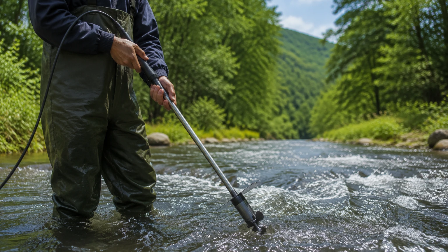
| Mechanical Propeller | ±2-5% of reading | 0.1 to 10 m/s | Submerged | High (Moving parts) |
Installation Considerations and Best Practices
Even the most advanced stream velocity meter will produce inaccurate data if installed incorrectly. Proper placement is the foundation of reliable hydraulic measurement.
Site Selection
The ideal installation site is a straight section of the channel with a uniform cross-section. Engineers should look for a location where the flow is laminar (smooth) and free from excessive turbulence. As a general rule, there should be a straight run of at least 10 times the channel width upstream and 5 times the channel width downstream from the sensor.
Mounting and Alignment
For radar sensors, the unit must be mounted securely to a bridge, boom, or cantilever arm. It should be perpendicular to the water surface or at the specific angle recommended by the manufacturer (often 30 to 45 degrees relative to the vertical). Any vibration in the mounting structure will introduce noise into the velocity signal.
For submerged sensors, the unit must be oriented directly into the flow. If the sensor is skewed even by a few degrees, the measured velocity will be lower than the actual velocity due to cosine error.
Integration with Level Measurement
Velocity alone does not provide flow volume (discharge). To calculate flow (Q = A × V), the cross-sectional area (A) must be known. This requires a simultaneous measurement of the water level. Integrating a stream velocity meter with a radar or ultrasonic level transmitter allows the system to calculate the wetted area in real-time and provide an accurate discharge reading in cubic meters per second (m³/s).
Limitations and Common Risks
Every measurement technology has "blind spots" that can lead to data errors or equipment failure.
* Turbulence and Aeration: Excessive white water or air bubbles can scatter radar and ultrasonic signals unpredictably. In highly turbulent zones, velocity readings may fluctuate wildly.
* Wind Interference: For non-contact radar meters, high winds can create surface ripples that do not reflect the actual bulk movement of the water. High-quality sensors use sophisticated algorithms to filter out wind-induced noise.
* Sedimentation and Fouling: Submerged sensors in wastewater or slow-moving natural streams are prone to siltation. If the sensor is covered in mud or algae, it will cease to function. Regular maintenance cycles are mandatory for submerged equipment.
* Minimum Depth: Most velocity meters require a minimum water depth to function. Radar needs enough surface area to reflect a signal, while submerged Doppler sensors require enough water cover (typically 50 mm to 100 mm) to avoid signal interference from the surface or the bed.
Frequently Asked Questions (FAQ)
Q1: Can a stream velocity meter measure flow in both directions?
Yes, many modern ultrasonic Doppler and electromagnetic meters are bi-directional. They can distinguish between forward flow and reverse flow, which is essential in tidal estuaries or irrigation systems with backflow potential.
Q2: How often should a stream velocity meter be calibrated?
For industrial applications, an annual calibration check is recommended. In environmental settings with high sediment, quarterly inspections may be necessary to ensure the sensor face is clean and the mounting hasn't shifted.
Q3: Is surface velocity always faster than the mean velocity?
In most open channels, yes. Due to friction against the channel bed and sides, the fastest flow is usually just below the surface in the center of the stream. The "index velocity" method is used to correlate the measured velocity to the average velocity of the entire cross-section.
Q4: Can these meters work in pipes?
Yes, but the pipe must not be completely full if using surface radar. If the pipe is pressurized and full, an inline electromagnetic or transit-time ultrasonic flowmeter is typically used instead of a stream velocity meter.
Conclusion
The selection of a stream velocity meter is a critical decision that impacts the efficiency of industrial processes and the accuracy of environmental data. By prioritizing non-contact methods like radar for high-maintenance or hazardous environments, and utilizing submerged Doppler or electromagnetic sensors for high-precision or low-flow requirements, engineers can build robust monitoring networks.
When combined with accurate level measurement, these instruments provide the necessary insights to manage water resources effectively, prevent flood damage, and optimize industrial throughput. For those seeking comprehensive instrumentation suites, the Main Page offers a gateway to advanced level and flow solutions tailored for professional engineering applications.