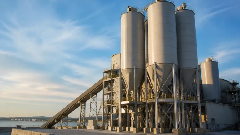
Boiler Conductivity Probe
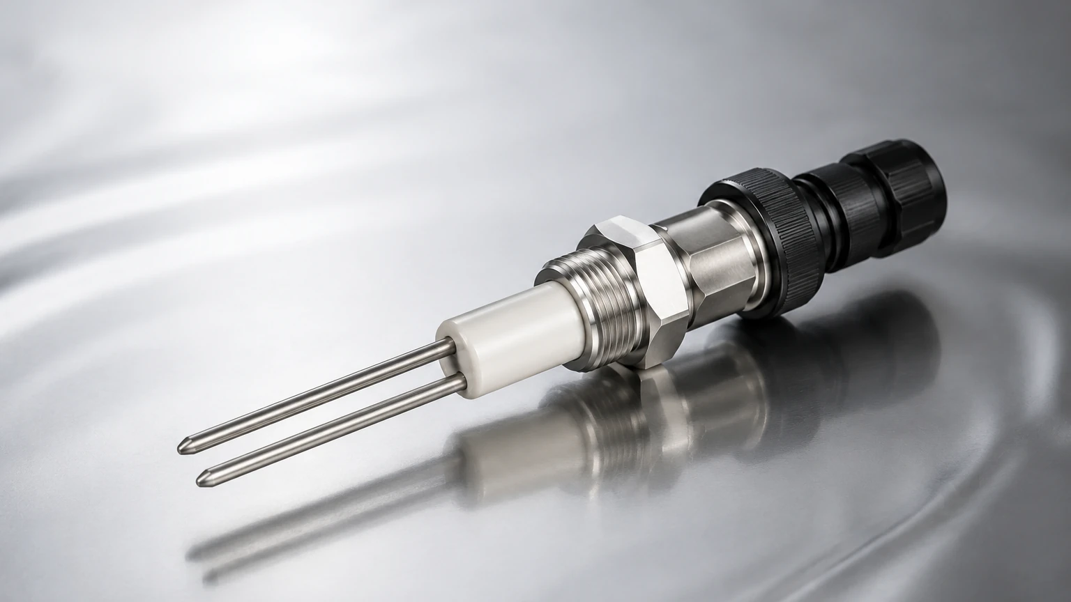
Boiler Conductivity Probe
In industrial steam generation, maintaining the chemical balance of boiler water is critical for both operational efficiency and equipment longevity. A boiler conductivity probe serves as the primary sensor for monitoring Total Dissolved Solids (TDS). As water evaporates into steam, dissolved minerals and salts remain behind, increasing in concentration. If left unmanaged, these solids lead to scale formation, foaming, and priming, which can damage turbines and heat exchangers. This article examines the technical principles, selection criteria, and installation requirements for conductivity probes in high-pressure boiler environments.
Measurement Principles of Boiler Conductivity
Conductivity is a measure of a liquid's ability to conduct an electrical current, which is directly proportional to the concentration of dissolved ionizable solids. In a boiler, the conductivity probe acts as the sensing element in a feedback loop that controls the blowdown process.
The Relationship Between TDS and Conductivity
While a probe measures electrical conductivity (typically in microsiemens per centimeter, µS/cm), the operator is ultimately interested in TDS (measured in ppm or mg/L). The relationship is generally expressed as:
TDS (mg/L) = Conductivity (µS/cm) × Conversion Factor
In boiler systems, this factor typically ranges from 0.7 to 0.9, depending on the specific chemistry of the feedwater and the boiler's operating pressure.
Electrode Physics and Cell Constants
The probe consists of two or more electrodes. When a voltage is applied, the ions in the water migrate toward the electrodes, creating a current. The physical geometry of the probe—specifically the distance between the electrodes ($L$) and their surface area ($A$)—defines the "cell constant" ($K = L/A$).
For boiler applications, a cell constant of $K=1.0$ is common, though $K=0.1$ may be used in high-purity condensate return lines. High-quality sensors, such as those integrated into broader industrial automation portfolios, must maintain a stable cell constant despite the harsh thermal and chemical environment of the boiler shell.
Technical Specifications and Selection Criteria
Selecting a boiler conductivity probe requires a deep understanding of the process conditions. Unlike standard process conductivity sensors, boiler probes must withstand high saturated steam temperatures and pressures.
Pressure and Temperature Ratings
Boiler probes are typically rated for specific pressure classes. Standard industrial boilers often operate between 10 bar (145 psi) and 32 bar (464 psi). For these applications, the probe body and insulation must be rated for at least 238°C (460°F) to handle saturated steam conditions. Advanced probes utilize stainless steel (316L) for the electrode body and high-performance polymers like PEEK (Polyether ether ketone) or PTFE (Polytetrafluoroethylene) for insulation.
Temperature Compensation
Conductivity is highly temperature-dependent; for every 1°C increase in temperature, conductivity typically increases by approximately 2%. Since boiler water temperatures fluctuate during load changes, the probe must include an integral temperature sensor (typically a Pt100 or Pt1000 RTD). The controller uses this data to provide "temperature-compensated conductivity," referenced to a standard temperature (usually 25°C).
Selection Table: Probe Characteristics by Boiler Type
| Boiler Category | Pressure Range (Metric) | Temperature Range | Recommended Material | Typical Cell Constant |
| :— | :— | :— | :— | :— |
| Low Pressure / HVAC | 0–10 bar | Up to 185°C | 316 SS / PTFE | 1.0 |
| Medium Pressure Industrial | 10–32 bar | Up to 239°C | 316 SS / PEEK | 1.0 |
| High Pressure / Power | >32 bar | >240°C | Special Alloys / Ceramic | 0.1 or 0.01 |
| Condensate Return | 0–5 bar | Up to 150°C | 316 SS / PTFE | 0.1 |
For engineers evaluating comprehensive fluid management systems, reviewing the Main Page of specialized manufacturers like Welk can provide insights into how conductivity sensing integrates with broader level measurement and automation strategies.
Installation Considerations
The accuracy of a boiler conductivity probe is heavily dependent on its placement. If the probe is installed in a "dead zone" where water circulation is poor, it will provide a lagging or inaccurate reading of the actual TDS levels.
Positioning and Orientation
1. Submergence: The probe must be installed below the lowest astronomical water level (LAWL) to ensure it is always in contact with the liquid phase. However, it should be positioned near the surface of the water, as this is where the highest concentration of dissolved solids typically occurs due to evaporation.
2. Proximity to Feedwater: The probe should be located away from the feedwater inlet. Fresh feedwater has significantly lower conductivity than the boiler bulk water; placing the probe too close will result in prematurely low readings and insufficient blowdown.
3. Steam Pockets: The probe should be installed horizontally or at a slight downward angle to prevent steam bubbles from becoming trapped against the electrode surface, which would cause erratic readings (air/steam is non-conductive).
Stilling Wells and Protection
In boilers with high internal turbulence, a stilling well (a perforated pipe surrounding the probe) may be necessary. This protects the probe from mechanical stress and ensures a stable liquid environment for measurement. The holes in the stilling well must be large enough to allow free circulation of water to ensure the sample remains representative.
Integration with Automatic Blowdown Systems
A boiler conductivity probe is rarely a standalone device; it is the "eyes" of the Automatic TDS Control System.
Continuous vs. Intermittent Blowdown
* Continuous Blowdown: The controller monitors the probe and modulates a motorized valve to maintain a steady, precise TDS level. This is the most efficient method for large industrial boilers.
* Intermittent (On/Off) Blowdown: The controller opens a solenoid valve when the conductivity exceeds a high setpoint and closes it once the level drops below a low setpoint. This is common in smaller systems.
By automating this process based on real-time probe data, facilities can significantly reduce water and fuel wastage. Over-blowing wastes treated water and heat energy, while under-blowing leads to scale and potential boiler failure.
Limitations and Maintenance
Despite their robust design, boiler conductivity probes are subject to several operational challenges that require regular attention.
Polarization and Fouling
In DC-based measurement systems, ions can build up near the electrodes, creating a "polarization" effect that increases resistance and lowers the apparent conductivity. To combat this, modern controllers use high-frequency AC signals. However, physical fouling—the buildup of scale or oil on the electrode surface—remains a risk. A fouled probe will always read lower than the actual TDS, which can lead to dangerous over-concentration of solids.
Flashing and Cavitation
If a probe is installed in a blowdown line rather than the boiler shell, there is a risk of "flashing." As the pressure drops across the blowdown valve, the water can turn to steam. Conductivity probes cannot measure steam; therefore, probes in blowdown lines must be installed upstream of the control valve or in a cooled sample line where the water remains in the liquid phase.
Calibration Procedures
Probes should be calibrated against a portable, calibrated conductivity meter. It is important to sample the boiler water through a sample cooler to bring the temperature down to a safe range (typically 25°C) before testing with a handheld device. If the probe and the handheld meter disagree, the probe's cell constant or temperature compensation factor may need adjustment in the controller.
Frequently Asked Questions (FAQ)
Q: How often should a boiler conductivity probe be cleaned?
A: This depends on the water quality. In well-managed systems, a quarterly inspection is usually sufficient. If the boiler experiences high hardness or oil contamination, monthly cleaning with a non-abrasive cloth and mild detergent may be required.
Q: Can I use a standard process conductivity probe in a boiler?
A: Generally, no. Standard probes are often rated only up to 60°C or 100°C. The high-pressure saturated steam environment of a boiler will quickly destroy the seals and insulation of a standard sensor, leading to leaks and electrical shorts.
Q: Why is my conductivity reading fluctuating wildly?
A: This is often caused by steam bubbles hitting the probe or the probe being partially uncovered due to surging water levels. Ensure the probe is fully submerged and check for the presence of a stilling well. It could also indicate electrical noise; ensure the probe cable is shielded and routed away from high-voltage power lines.
Q: What is the difference between a 2-pole and 4-pole probe for boilers?
A: 2-pole probes are standard and suitable for most boiler applications. 4-pole probes are more resistant to fouling and polarization because they use separate pairs of electrodes for current drive and voltage sensing, making them ideal for very high-conductivity or high-fouling environments.
Conclusion
The boiler conductivity probe is a small but vital component in the industrial steam loop. By providing the data necessary for precise TDS control, it protects the boiler from scale and corrosion while optimizing energy use. When selecting a probe, engineers must prioritize pressure and temperature ratings, material compatibility, and correct physical placement within the boiler shell. For those seeking comprehensive solutions in level and flow measurement, manufacturers like Welk offer the technical expertise required to integrate these sensors into a reliable industrial automation framework. Proper installation and regular calibration remain the cornerstones of a safe and efficient boiler room operation.