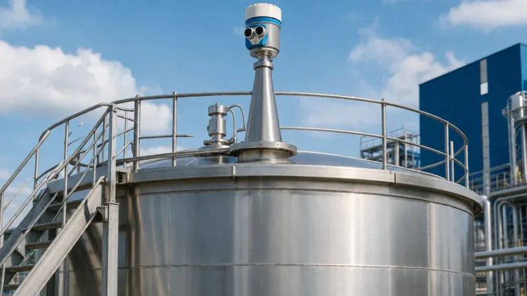
Microwave Radar Level Transmitter
Microwave Radar Level Transmitter: A Comprehensive Engineering Guide to Radar Measurement
In modern industrial automation, the requirement for precise, non-contact level measurement has led to the widespread adoption of the microwave radar level transmitter. Unlike ultrasonic sensors that rely on sound waves and are susceptible to air temperature and pressure changes, radar technology utilizes electromagnetic waves. These waves travel at the speed of light and are virtually unaffected by the process atmosphere, making them the preferred choice for complex industrial environments.
Professional engineers and procurement specialists must understand the underlying physics, frequency variations, and installation constraints to ensure the long-term reliability of these instruments. This guide examines the technical foundations of Radar Level Meters and provides a practical framework for selecting the appropriate technology for specific process applications.
1. Measurement Principles of Microwave Radar
A microwave radar level transmitter operates by emitting high-frequency electromagnetic pulses (microwaves) toward the surface of the medium being measured. When these waves encounter a change in the dielectric constant ($ε_r$) at the interface between the air and the process medium, a portion of the energy is reflected back to the sensor's antenna.
Time of Flight (ToF) and Signal Processing
The fundamental principle used in most radar level measurement is Time of Flight. The instrument measures the time interval ($t$) between the emission of the pulse and the reception of the echo. Since the speed of light ($c$) is a known constant, the distance ($D$) to the material surface is calculated using the formula:
$$D = \frac{c \times t}{2}$$
The level ($L$) is then determined by subtracting the distance ($D$) from the total tank height ($H$).
Pulse Radar vs. FMCW Radar
There are two primary methods for processing these microwave signals:
1. Pulse Radar: This method sends out short microwave pulses and measures the time delay of the returning echo. It is known for its lower power consumption and is often used in simpler, battery-powered or loop-powered applications. However, it may struggle with low-dielectric media or turbulent surfaces.
2. Frequency Modulated Continuous Wave (FMCW): In FMCW technology, the transmitter emits a continuous signal with a constantly changing frequency (a linear sweep). The reflected signal is compared to the signal being emitted at that exact moment. The difference in frequency is directly proportional to the distance. FMCW provides significantly higher accuracy (often down to ±1 mm) and better signal-to-noise ratios, making it ideal for high-precision custody transfer and difficult process conditions.
2. The Role of the Dielectric Constant ($ε_r$)
The effectiveness of a microwave radar level transmitter is heavily dependent on the dielectric constant of the material. The dielectric constant is a measure of a material's ability to reflect electromagnetic energy.
* High Dielectric Media (ε_r > 10): Water-based liquids, acids, and alkalis reflect radar signals very well, allowing for easy measurement even with high turbulence.
* Low Dielectric Media (ε_r < 3): Hydrocarbons, oils, and certain solids (like plastic pellets) absorb or allow much of the radar energy to pass through. Measuring these materials requires higher-sensitivity electronics, larger antennas, or the use of Guided Wave Radar (GWR).
When the dielectric constant is extremely low (e.g., ε_r < 1.4), the signal may penetrate the material and reflect off the bottom of the tank, leading to false readings if the software does not account for the "bottom echo."
3. Frequency Bands and Antenna Selection
The frequency at which a microwave radar level transmitter operates determines its beam angle and its ability to penetrate foam or dust. Common industrial frequencies include:
* 6 GHz (C-Band): These low-frequency radars are less affected by foam or heavy condensation on the antenna. However, they require large antennas (up to 250 mm) to achieve a narrow beam, making them unsuitable for small vessels.
* 26 GHz (K-Band): This is the industry standard for most liquid applications. It offers a good balance between antenna size and beam focus. It is effective in most chemical and water treatment tanks.
* 80 GHz (W-Band): The current state-of-the-art in radar technology. Because of the high frequency, the beam angle can be as narrow as 3°. This allows the radar to avoid internal obstructions like agitators or ladders and makes it possible to measure through narrow nozzles or small-diameter tanks.
Selection Table: Technology Comparison
| Feature | Pulse Radar (26 GHz) | FMCW Radar (80 GHz) | Guided Wave Radar (GWR) |
| :— | :— | :— | :— |
| Accuracy | ±3 mm to ±5 mm | ±1 mm | ±2 mm |
| Beam Angle | 8° – 20° | 3° – 6° | N/A (Conducted) |
| Dust Resistance | Moderate | High | Excellent |
| Foam Resistance | Low | Moderate | Excellent |
| Internal Obstructions | High Interference | Low Interference | Ignores Obstructions |
| Max Range | 30 meters | 120 meters | 75 meters |
4. Installation Considerations and Constraints
Correct installation is critical for the performance of any microwave radar level transmitter. Even the most advanced 80 GHz sensor will fail if placed incorrectly. Engineers should adhere to the following guidelines:
Nozzle Geometry
The antenna should ideally extend slightly beyond the bottom of the mounting nozzle to prevent "ringing" or internal reflections within the nozzle. If the nozzle is very long, a higher frequency radar with a narrower beam is required to prevent the signal from hitting the nozzle walls.
Avoiding Obstructions
The radar beam spreads as it travels. Any metal object within the beam path—such as heating coils, agitator blades, or support struts—will create a "false echo." Modern transmitters include "False Echo Suppression" software, allowing the user to map out these static reflections so the sensor ignores them. However, it is always better to install the sensor in a location with a clear line of sight to the product surface.
Dead Zones (Blocking Distance)
Every radar has a minimum measurement distance, known as the dead zone or blocking distance, typically ranging from 50 mm to 300 mm from the antenna tip. If the level rises into this zone, the transmitter will report an error or hold the last known value. Engineers must ensure the tank's maximum fill level does not enter this zone.
Positioning on the Tank
* Wall Distance: Do not mount the sensor too close to the tank wall. Reflections from the wall can interfere with the signal. A rule of thumb is to maintain a distance of at least 1/6th of the tank diameter from the wall.
* Central Mounting: Avoid mounting the sensor in the exact center of a domed or conical tank, as this can cause multiple reflections to converge at the antenna, creating signal noise.
* Inlet Streams: Never install the sensor directly above the filling inlet, as the falling product will interfere with the microwave signal.
5. Application-Specific Challenges
While highly versatile, microwave radar level transmitters face specific challenges in certain industrial environments:
Foam and Turbulence
Heavy, dense foam can absorb microwave signals, leading to signal loss. In applications with heavy foam (e.g., fermentation or certain chemical reactions), Guided Wave Radar or low-frequency (6 GHz) radar is often more effective. Turbulence on the liquid surface can scatter the signal; however, FMCW processing and averaging algorithms can usually compensate for this to maintain a stable reading.
High Pressure and Temperature
In oil and gas or steam applications, the dielectric constant of the gas space above the liquid can change significantly with pressure and temperature. This affects the speed of light and can introduce measurement errors. High-end transmitters include compensation factors for these changes. For extreme temperatures (up to 450°C), specialized cooling fins or ceramic seals are utilized to protect the electronics.
Solids and Dust
Measuring the level of bulk solids (grain, cement, ore) is more difficult than measuring liquids. Solids often have an angle of repose, which reflects the signal away from the antenna. Furthermore, heavy dust during filling can attenuate the signal. 80 GHz radars are particularly effective here because their high frequency allows them to penetrate dust clouds more efficiently than ultrasonic sensors.
6. Maintenance and Troubleshooting
Microwave radar level transmitters are generally low-maintenance because they have no moving parts. However, certain issues may arise:
1. Antenna Buildup: In sticky or crystallizing media, material may accumulate on the antenna. While many radars can "see through" a thin layer of coating, heavy buildup will eventually block the signal. Self-cleaning PTFE covers or air-purge connections can mitigate this.
2. Signal Loss: If the transmitter suddenly reports "Loss of Echo," check for physical changes in the tank, such as a new agitator or a change in the chemical composition of the medium (lowering the dielectric constant).
3. Accuracy Drift: Radar accuracy does not typically drift. If readings are inaccurate, it is usually due to an incorrect "Zero" or "Full" calibration point in the setup software, or a change in the vapor space density in high-pressure vessels.
7. Procurement Checklist for International Buyers
When sourcing a microwave radar level transmitter for industrial projects, confirm the following technical specifications with the manufacturer:
* Medium Properties: What is the minimum dielectric constant of the product? Is there foam, agitation, or dust?
* Process Conditions: What are the maximum and minimum operating pressures (in bar) and temperatures (°C)?
* Vessel Geometry: Provide the tank height, nozzle diameter, and nozzle length. Are there internal obstructions?
* Output Requirements: Is the standard 4-20mA HART sufficient, or is a digital protocol like Modbus, Profibus, or Foundation Fieldbus required?
* Certifications: Does the environment require explosion-proof (Ex-d) or intrinsically safe (Ex-ia) ratings? For water treatment, are food-grade or hygienic certifications necessary?
8. Frequently Asked Questions (FAQ)
Q: Can a radar level meter measure through a plastic tank wall?
A: Yes. Microwaves can penetrate non-conductive materials like plastic (HDPE, PVC) or glass. This allows for "non-intrusive" measurement where the sensor is mounted outside the tank, looking through a window or the tank roof.
Q: How does radar compare to ultrasonic level sensors?
A: Radar is superior in vacuum, high pressure, high temperature, and environments with dust or vapor. Ultrasonic sensors are only recommended for simple, ambient-pressure water applications where cost is the primary driver.
Q: Is radar safe for human operators?
A: Yes. The microwave energy emitted by an industrial radar transmitter is extremely low—significantly lower than that of a mobile phone. It is safe for continuous operation in areas where personnel are present.
Q: What is the maximum range of a microwave radar level transmitter?
A: Standard industrial radars can measure up to 30 or 70 meters. Specialized high-frequency FMCW units can reach distances of up to 120 meters, making them suitable for large silos and tall storage tanks.
Conclusion
The microwave radar level transmitter represents the pinnacle of level measurement technology for the process industries. By understanding the interaction between microwave frequency, dielectric constants, and tank geometry, engineers can implement solutions that provide millimeter-level accuracy in the most demanding conditions. Whether for water treatment, chemical processing, or oil and gas storage, selecting the right radar instrument is a balance of technical capability and application-specific requirements. For those seeking reliable, long-term performance, investing in high-frequency FMCW technology often provides the best return on investment through reduced maintenance and increased process uptime.