Vega Radar Level Transmitter Model Number
Understanding Vega Radar Level Transmitter Model Number Selection for Industrial Applications
In the field of industrial process automation, selecting the correct instrumentation is critical for operational safety and efficiency. Among the most versatile tools for liquid and solid level measurement are non-contact radar sensors. When engineers and procurement specialists evaluate a vega radar level transmitter model number, they are not just looking at a part identifier; they are deciphering a complex configuration string that defines the device’s frequency, antenna design, pressure rating, and signal output.
This guide provides a technical overview of how radar level transmitters operate, how to interpret model configurations, and the critical factors that influence selection for demanding industrial environments. For those seeking high-performance alternatives for various process conditions, exploring modern Radar Level Meters provides a benchmark for accuracy and reliability in the global market.
Measurement Principles of Radar Level Technology
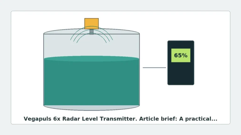
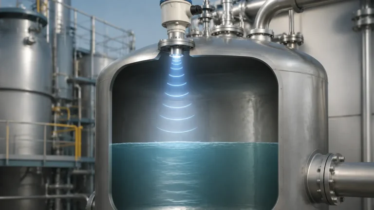
Before diving into specific model numbers, it is essential to understand the underlying physics that dictate sensor performance. Radar level transmitters generally utilize two primary methods of measurement: Pulse Radar and Frequency Modulated Continuous Wave (FMCW).
Pulse Radar (Time-of-Flight)
Pulse radar sensors emit short microwave pulses toward the medium. The sensor measures the time it takes for the pulse to travel to the surface and reflect back to the antenna. The distance ($D$) is calculated as $D = (c \times t) / 2$, where $c$ is the speed of light and $t$ is the transit time. This technology is robust and energy-efficient, often used in simpler liquid applications.
FMCW (Frequency Modulated Continuous Wave)
Modern high-end radar transmitters, such as the 80 GHz series, typically use FMCW technology. Instead of pulses, the transmitter sends a continuous signal with a constantly changing frequency. The difference in frequency between the transmitted signal and the reflected signal is proportional to the distance. FMCW offers significantly higher resolution and signal-to-noise ratios, making it the preferred choice for measuring solids or liquids with low dielectric constants.
Decoding the Vega Radar Level Transmitter Model Number
A typical model number for a radar transmitter is a modular code. Each segment of the alphanumeric string corresponds to a specific hardware or software feature. While specific codes change as product lines evolve (such as the transition from the VEGAPULS 60 series to the VEGAPULS 6X), the logic remains consistent.
1. The Series Identifier
The first part of the model number usually indicates the core technology and frequency range:
* 80 GHz (e.g., VEGAPULS 64/69/6X): High-frequency sensors with narrow beam angles, ideal for small tanks or vessels with internal obstructions.
* 26 GHz (e.g., VEGAPULS 61/62/63): Mid-frequency sensors suitable for standard liquid applications and larger silos.
* 6 GHz (e.g., VEGAPULS 65/66): Low-frequency sensors used in applications with heavy foam or extreme steam, where longer wavelengths can penetrate surface turbulence.
2. Antenna Type and Material
The antenna is the interface between the electronics and the process. Model numbers specify whether the unit uses a plastic horn antenna, a stainless steel flange with a PTFE cover, or a hygienic encapsulated antenna for food and beverage applications.
3. Process Connection and Pressure Rating
This section of the model number defines how the sensor attaches to the vessel. Options include threaded connections (e.g., G1½, 1½ NPT) or flanged connections (e.g., DN80, ANSI 3"). The code also dictates the pressure limits, ranging from vacuum to over 160 bar (2,320 psi).
4. Electronics and Signal Output
Finally, the model number specifies the communication protocol. Common options include:
* 4…20 mA/HART: The industry standard for analog integration.
* Profibus PA / Foundation Fieldbus: For digital plant architectures.
* Modbus / Bluetooth: For remote monitoring and easy commissioning via mobile devices.
Selection Criteria: Choosing the Right Configuration
Selecting a transmitter based on a model number requires matching the device specifications to the physical properties of the medium and the vessel geometry.
Dielectric Constant ($ε_r$)
The dielectric constant of the material determines how much energy is reflected back to the sensor. Hydrocarbons (oil, diesel) have low $ε_r$ values (~2.0), requiring more sensitive electronics or larger antennas. Water-based liquids have high $ε_r$ values (~80) and are much easier to measure.
Comparison Table: Frequency vs. Application
| Frequency | Typical Beam Angle | Best For | Limitations |
| :— | :— | :— | :— |
| 80 GHz | 3° to 8° | Small vessels, narrow nozzles, solids with dust. | Higher cost; sensitive to heavy condensation build-up. |
| 26 GHz | 10° to 20° | General purpose liquids, large storage tanks. | Wider beam may hit internal obstructions (ladders, agitators). |
| 6 GHz | 20°+ | Extreme foam, steam, or turbulent surfaces. | Large antenna required; very wide beam angle. |
Installation Considerations and Constraints
Even the most advanced vega radar level transmitter model number will fail to perform if installation constraints are ignored. Engineers must adhere to the following guidelines:
1. Blocking Distance (Dead Zone): Every radar sensor has a minimum distance (typically 50 mm to 200 mm) from the antenna tip where measurements are not possible. Ensure the maximum fill level does not enter this zone.
2. Nozzle Dimensions: The nozzle height should be kept as short as possible. If a nozzle is too long or narrow, the radar signal may reflect off the nozzle wall, creating a "ringing" effect that masks the true level.
3. Beam Path Clearance: The "beam angle" is defined as the point where the signal power drops by 50% (-3dB). However, energy still exists outside this angle. The beam path must be clear of agitators, heating coils, and ladders. If obstructions are unavoidable, most modern Radar Level Meters allow for "False Signal Suppression" to map out and ignore these static reflections.
4. Orientation: For solid materials, the sensor should ideally be mounted with an aiming flange to tilt the beam toward the angle of repose of the material, ensuring the best possible reflection back to the antenna.
Limitations and Application Risks
While radar is often considered the "universal" solution, it has specific limitations:
* Heavy Foam: Dense, thick foam can absorb the radar signal entirely. In such cases, 6 GHz sensors or hydrostatic pressure transmitters may be more appropriate.
* Vacuum Conditions: While radar works in a vacuum (unlike ultrasonic sensors), the seal materials specified in the model number must be rated for vacuum service to prevent air ingress or sensor damage.
* Multiple Interfaces: Radar primarily reflects off the top surface. If you need to measure the interface between oil and water, Guided Wave Radar (GWR) is typically required instead of non-contact radar.
Frequently Asked Questions (FAQ)
Q: Can I use a liquid radar model for solids measurement?
A: It depends on the model. 80 GHz sensors are often cross-compatible, but solids measurement usually requires higher dynamic range and specific software algorithms to handle the uneven surfaces and dust typical of silos. Always check if the model number specifies "Solids" or "Liquids."
Q: What does the "IP" rating in the model number mean?
A: This indicates the Ingress Protection. For most industrial environments, IP66/67 is standard. For submerged applications or wash-down areas, IP68 is required.
Q: How does temperature affect the model selection?
A: Radar electronics are sensitive to heat. If the process temperature exceeds 80°C (176°F), the model number must specify a high-temperature version with a cooling spacer or a specialized antenna seal (like Kalrez) that can withstand temperatures up to 250°C or higher.
Q: Is it possible to change the output signal after purchase?
A: Generally, no. The electronics module is a fixed part of the model configuration. If you order a 4-20mA HART unit and later require Modbus, you would typically need to replace the electronics insert or use a signal converter.
Summary for International Buyers
When requesting a quote or specifying a unit, providing the full vega radar level transmitter model number ensures that the manufacturer accounts for every environmental variable. For projects requiring customized OEM/ODM services or cost-effective alternatives that meet the same rigorous engineering standards, Welk offers a range of Radar Level Meters designed for water treatment, chemical processing, and oil and gas automation.
By understanding the relationship between frequency, antenna design, and process conditions, engineers can ensure long-term reliability and minimize maintenance costs in their level measurement applications.