Non Contact Radar Level Transmitter Endress Hauser
Non Contact Radar Level Transmitter Endress Hauser: An Engineering Selection Guide
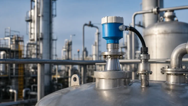
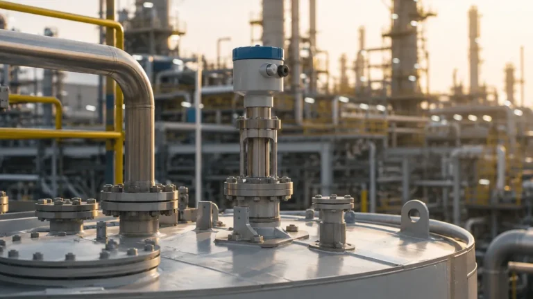
In the landscape of industrial process automation, the ability to accurately monitor liquid and solid levels without physical contact is a critical requirement for safety, efficiency, and inventory management. The non contact radar level transmitter Endress Hauser (specifically the Micropilot series) has established itself as an industry standard for these applications. By utilizing electromagnetic waves, these instruments provide high-precision measurements in environments where traditional contact-based sensors—such as floats or displacers—would fail due to corrosion, coating, or mechanical wear.
For process engineers and procurement specialists, selecting the correct radar instrument requires a deep understanding of the underlying physics, the specific constraints of the vessel, and the dielectric properties of the medium being measured. This guide explores the technical foundations of non-contact radar technology and provides a framework for selecting and installing these devices in demanding industrial environments.
1. Measurement Principles: How Non-Contact Radar Works
Before selecting a specific model, it is essential to understand the two primary methods used by Radar Level Meters to determine distance: Pulse Radar (Time of Flight) and Frequency Modulated Continuous Wave (FMCW).
Time of Flight (ToF)
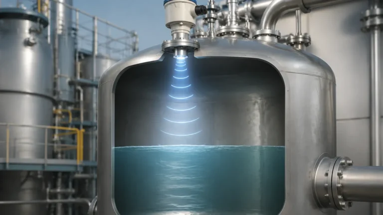
Pulse radar transmitters emit short microwave pulses toward the product surface. The signal travels at the speed of light, reflects off the surface of the medium, and returns to the antenna. The transmitter’s electronics measure the time elapsed between the emission and the reception. Since the speed of light is constant, the distance (D) is calculated as:
D = (c × t) / 2
Where *c* is the speed of light and *t* is the transit time. The level (L) is then derived by subtracting the distance from the known tank height (E).
Frequency Modulated Continuous Wave (FMCW)
Modern high-end transmitters, such as the Micropilot FMR6x series, often utilize FMCW technology. Instead of pulses, the instrument emits a continuous signal with a constantly changing frequency. When the reflected signal is received, it is compared to the frequency being emitted at that exact moment. The frequency difference (Δf) is directly proportional to the distance. FMCW is generally considered superior for high-accuracy applications and environments with significant noise or turbulence, as it provides a higher signal-to-noise ratio.
2. Frequency Selection and Its Impact on Performance
The frequency at which a radar transmitter operates determines its beam angle, sensitivity, and ability to penetrate foam or dust. Non-contact radar transmitters typically operate in three main frequency bands:
* 6 GHz (C-Band): These instruments have a wide beam angle and are less affected by foam, steam, or heavy turbulence. They are ideal for large tanks with internal obstructions where the surface might be agitated.
* 26 GHz (K-Band): The most common "all-rounder" frequency. It offers a balance between a narrow beam and a manageable antenna size. It is suitable for a wide range of liquids and some solids.
* 80 GHz (W-Band): The latest evolution in radar technology. Operating at 80 GHz allows for extremely small antenna designs and a very narrow beam angle (often as low as 3°). This is critical for tall, narrow silos or tanks with many internal obstructions like agitators or heating coils.
3. The Micropilot Series: Engineering Features
Endress+Hauser categorizes its non-contact radar transmitters under the Micropilot brand. Each sub-series is engineered for specific industrial challenges:
* Micropilot FMR10/FMR20: Designed for the water and wastewater industry. These are compact, cost-effective units with Bluetooth commissioning, typically used for open channels or plastic tanks.
* Micropilot FMR5x Series: The workhorse of the chemical and oil and gas industries. This series includes models like the FMR51 (liquids), FMR52 (corrosive liquids with PTFE-filled horn), and FMR57 (solids).
* Micropilot FMR6x Series: Utilizing 80 GHz technology, these units are designed for high-precision liquid measurement (FMR60/62) or complex bulk solids (FMR67). They often feature "Heartbeat Technology," which allows for in-situ verification of the device's health without interrupting the process.
4. Practical Selection Table
When choosing a non contact radar level transmitter Endress Hauser, use the following table as an initial engineering reference:
| Application | Recommended Model | Frequency | Key Advantage |
| :— | :— | :— | :— |
| Basic Water/Wastewater | FMR20 | 26 GHz | IP68 rating, cost-effective |
| Corrosive Chemicals | FMR52 | 26 GHz | Flush-mounted PTFE antenna |
| High-Pressure Liquids | FMR54 | 6 GHz | Planar antenna for stilling wells |
| Small Tanks / Agitators | FMR60 | 80 GHz | Narrow beam avoids obstructions |
| Large Grain Silos | FMR67 | 80 GHz | Penetrates heavy dust |
| High Temp (up to +450°C) | FMR51 | 26/6 GHz | High-temperature ceramic feed |
5. Installation Considerations and Constraints
Even the most advanced radar transmitter will fail if installed incorrectly. Engineers must adhere to strict geometric constraints to ensure a clear signal return.
Beam Angle and Obstructions
The "blocking distance" and the beam spread are the most critical factors. The radar beam expands as it travels. If the beam hits a ladder, a heating pipe, or the tank wall, it will create a "false echo."
* Rule of Thumb: Keep the beam path clear of any metallic objects. If an obstruction is unavoidable, most modern transmitters allow for "False Echo Mapping," where the software is taught to ignore specific static reflections.
Nozzle Height and Diameter
The antenna must protrude through the nozzle into the tank, or the nozzle must be wide enough to prevent the beam from reflecting off the nozzle walls. For 80 GHz units, nozzle interference is significantly reduced, but for 6 GHz or 26 GHz units, the nozzle height-to-diameter ratio must be carefully checked against the manufacturer's data sheet.
Mounting Position
* Avoid the center: Never mount the transmitter in the exact center of a cylindrical tank, as this can lead to multiple reflections that amplify noise.
* Avoid the wall: Maintain a minimum distance from the wall (typically 1/6th of the tank diameter) to prevent signal interference.
* Avoid the inlet: Ensure the transmitter is not located directly above the product inflow, as the falling stream will cause erratic readings.
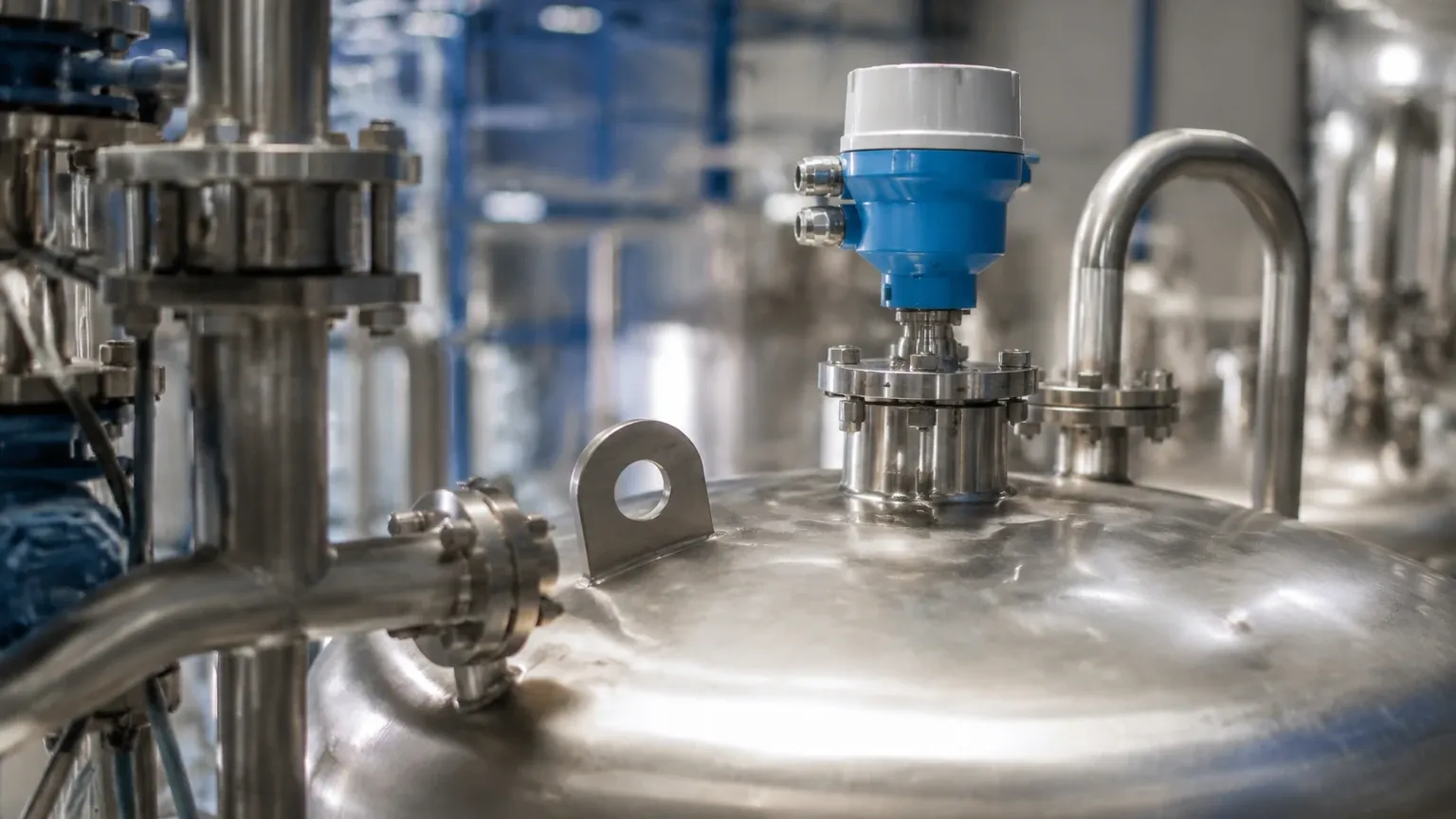
6. Limitations and Application Risks
While non-contact radar is highly versatile, it is not a universal solution. Engineers must account for the following limitations:
1. Dielectric Constant (DC): Radar depends on the reflection of waves. Materials with a very low dielectric constant (e.g., liquefied gases or certain oils with DC < 1.4) reflect very little energy. In these cases, a guided wave radar or a stilling well may be required.
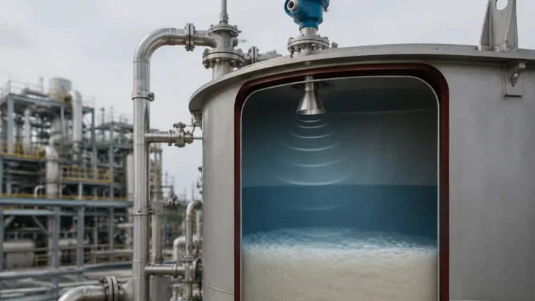
2. Heavy Foam: While 6 GHz radar can penetrate some foam, extremely dense, thick foam (like shaving cream) can absorb the radar signal entirely, leading to a "loss of echo" error.
3. Vacuum and Pressure: While the radar signal itself is unaffected by vacuum or pressure, the mechanical seals and the ceramic or glass feed-throughs of the transmitter must be rated for the specific process conditions. Extreme pressures can also slightly alter the propagation speed of the signal, though this is usually compensated for in the device settings.
7. International Buyer’s Checklist
If you are sourcing a non contact radar level transmitter Endress Hauser for an international project, ensure the following technical specifications are confirmed before purchase:
* Process Connection: Confirm if you require DIN, ANSI, or JIS flanges. Metric vs. Imperial threading (NPT vs. G) is a common source of installation delays.
* Output Protocol: Does the site use 4-20mA HART, PROFIBUS PA, FOUNDATION Fieldbus, or Modbus?
* Hazardous Area Approvals: Ensure the device carries the correct certification for the region (ATEX for Europe, FM/CSA for North America, IECEx for international).
* Material Compatibility: Verify that the wetted parts (316L Stainless Steel, PTFE, Kalrez, etc.) are compatible with the process medium.
* Calibration Range: Specify the "Zero" and "Span" points, though these can usually be adjusted in the field via the display or a digital interface.
8. Frequently Asked Questions (FAQs)
Q: Can non-contact radar measure through a plastic tank lid?
A: Yes. Since plastic is non-conductive, microwaves can pass through it. This allows for "tank-side" measurement where the sensor is mounted outside a plastic IBC or storage tank, provided the plastic is not carbon-filled or metallic-coated.
Q: How does 80 GHz radar handle condensation on the antenna?
A: 80 GHz transmitters like the Micropilot FMR60 often use a convex (dripping) lens antenna made of PTFE. This shape, combined with the high frequency, makes the device much more resistant to the effects of condensation compared to older horn antenna designs.
Q: What is the difference between "Non-Contact Radar" and "Ultrasonic" level sensors?
A: Ultrasonic sensors use sound waves, which require air as a medium. They are affected by temperature fluctuations, wind, and vacuum. Radar uses electromagnetic waves, which work in a vacuum and are largely unaffected by air temperature or pressure changes, making radar more reliable for process tanks.
Q: Is maintenance required for these transmitters?
A: Generally, no. Because there are no moving parts and no contact with the media, maintenance is minimal. However, in applications with heavy buildup or crystallization, periodic cleaning of the antenna face may be necessary to prevent signal attenuation.
Conclusion
The selection of a non contact radar level transmitter Endress Hauser represents a significant investment in process reliability. By matching the frequency (6, 26, or 80 GHz) to the specific vessel geometry and medium properties, engineers can achieve millimeter-precision measurement that lasts for decades. Whether dealing with the extreme dust of a cement silo or the corrosive environment of a chemical reactor, the Micropilot range offers a specialized solution. For further technical comparisons and alternative hardware options, reviewing the broader range of Radar Level Meters can provide additional perspective on cost-to-performance ratios for your specific industrial application.
Download Non Contact Radar Level Transmitter Endress Hauser as a PDF