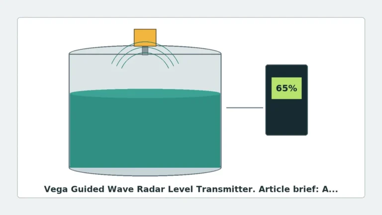
Frequency of Guided Wave Radar Level Transmitter
Frequency of Guided Wave Radar Level Transmitter: A Technical Engineering Guide
In the landscape of industrial process automation, selecting the correct level measurement technology is critical for operational safety and efficiency. Among the various technologies available, Guided Wave Radar (GWR) has emerged as a robust solution for challenging environments. A fundamental technical parameter that engineers must understand when specifying these instruments is the frequency of guided wave radar level transmitter systems. Unlike non-contact radar, which relies on high-frequency air propagation, GWR utilizes a physical waveguide to direct electromagnetic pulses, leading to distinct frequency requirements and performance characteristics.
This guide examines the measurement principles of GWR, the significance of operating frequencies, and practical selection criteria for industrial applications. For professionals seeking high-performance instrumentation, understanding these nuances is essential when evaluating Radar Level Meters for complex process vessels.
Measurement Principles: Time Domain Reflectometry (TDR)
Guided Wave Radar operates on the principle of Time Domain Reflectometry (TDR). The instrument generates low-energy electromagnetic pulses that are transmitted along a probe (the waveguide). When these pulses encounter a medium with a different dielectric constant ($ε_r$) than the one they are currently traveling through (usually air or vapor), a portion of the pulse energy is reflected back to the transmitter.
The Role of Frequency in TDR
In GWR technology, the "frequency" typically refers to the spectral content of the narrow pulses emitted by the transmitter. Most industrial GWR units utilize pulses with a frequency spectrum centered between 100 MHz and 1.8 GHz.
The transmitter measures the time-of-flight—the interval between the pulse emission and the reception of the reflected signal. Since the speed of light in a vacuum (and approximately in air) is constant, the distance to the product surface is calculated using the formula:
$$D = \frac{c \times t}{2}$$
Where:
- $D$ is the distance to the surface.
- $c$ is the speed of light.
- $t$ is the measured transit time.
The lower frequency range of GWR compared to non-contact radar (which often operates at 26 GHz or 80 GHz) allows the signal to travel efficiently along the probe with minimal attenuation, making it ideal for materials with low dielectric constants or applications involving heavy steam and foam.
Understanding the Frequency of Guided Wave Radar Level Transmitter
The frequency of guided wave radar level transmitter equipment is specifically engineered to balance signal resolution with the ability to penetrate vapors and resist coating. While non-contact radar focuses on beam divergence and antenna size (where higher frequency equals a narrower beam), GWR frequency focuses on the pulse's ability to follow the waveguide and reflect accurately at the interface.
Frequency vs. Signal Integrity
1. Pulse Width and Resolution: Higher frequency components within the TDR pulse allow for shorter pulse widths. Shorter pulses result in a smaller "dead zone" (the area at the top of the probe where measurement is not possible) and better resolution between closely spaced targets, such as the interface between two liquids.
2. Attenuation: Lower frequencies are generally less susceptible to signal loss caused by the physical properties of the probe or the environment (such as high-viscosity coatings on the probe). However, if the frequency is too low, the pulse may not reflect efficiently from low-dielectric surfaces.
3. Electromagnetic Compatibility (EMC): Because the signal is guided, GWR is inherently less likely to cause or receive interference compared to open-air radar. This allows GWR to operate effectively in narrow nozzles and small tanks where high-frequency non-contact radar might suffer from false echoes.
Technical Selection Criteria
When selecting a GWR transmitter, the operating frequency and probe design must be matched to the specific process media. The following table provides a general selection framework for common industrial scenarios.
Selection Table: Probe Type and Application
| Application Type | Recommended Probe | Dielectric Constant (ε_r) | Frequency Considerations |
| :— | :— | :— | :— |
| Clean Liquids (Water/Acids) | Single Rod / Cable | > 1.4 | Standard 1 GHz range; high signal-to-noise ratio. |
| Low Dielectric (Oils/Solvents) | Coaxial Probe | > 1.1 | Coaxial design concentrates the pulse, maximizing reflection. |
| Solid Granules / Powders | Heavy Duty Cable | > 1.6 | Lower frequency pulses handle signal scattering better. |
| Interface Measurement | Coaxial or Dual Rod | Difference > 0.1 | Requires high-resolution pulses to distinguish interface peaks. |
| High Temperature/Pressure | Single Rod with Seal | > 1.4 | Specialized ceramic seals affect pulse propagation; frequency tuning required. |
Installation Considerations and Best Practices
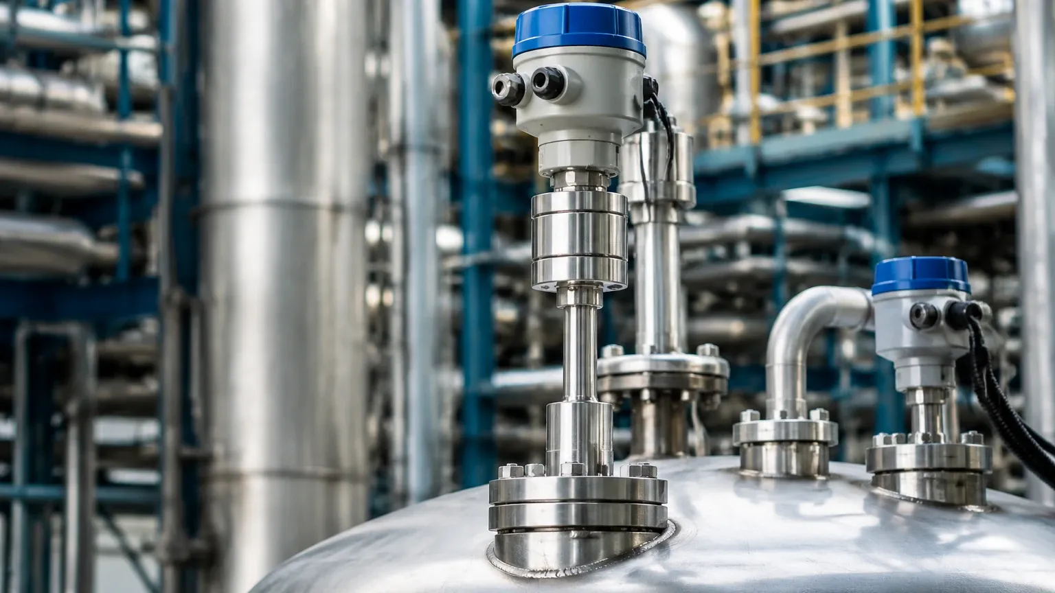
To ensure the frequency of guided wave radar level transmitter signals remains stable and accurate, proper installation is paramount. Unlike non-contact sensors, the physical probe of a GWR unit interacts directly with the tank environment.
1. Nozzle Geometry
The diameter and height of the mounting nozzle can influence the initial pulse. If the nozzle is too narrow or too long, it may create a "ringing" effect that masks the signal near the top of the tank. For single-rod probes, a nozzle diameter of at least 50 mm (2 in) is typically recommended.
2. Obstruction Clearance
While the signal is guided, an electromagnetic field still extends around the probe. This is known as the "radial detection zone." For a single-rod probe, any metallic object (ladders, agitators, or pipes) within 300 mm (12 in) of the probe can cause interference. Coaxial probes are immune to this, as the electromagnetic field is entirely contained within the outer tube.
3. Probe Length and Tensioning
In tall silos or deep sumps, cable probes are used. These must be properly weighted or anchored to prevent the cable from swinging into tank walls or internal structures, which would disrupt the guided signal. If the probe touches a grounded metal surface, the signal will be lost.
4. Dead Zones (Blocking Distance)
Every GWR has an upper and lower dead zone. The upper dead zone (typically 50 mm to 200 mm) is where the pulse is generated and stabilized. The lower dead zone occurs at the end of the probe where the signal dissipates. Engineers must ensure the maximum and minimum process levels fall within the active measuring range of the probe.
Limitations and Application Risks
Despite its versatility, Guided Wave Radar is not a universal solution. Certain conditions can degrade the performance of the guided pulse.
* Extremely Low Dielectric Media: Materials with a dielectric constant below 1.1 (such as liquid helium or some pure liquefied gases) may not reflect enough energy for a reliable measurement. In these cases, a "bottom-up" measurement or a coaxial probe is required.
* Heavy Coating and Bridging: While GWR can handle some coating, significant buildup that "bridges" the gap between a dual-rod probe or fills the space in a coaxial probe will cause false high-level readings. Single-rod probes are more resistant to this but still require periodic cleaning in sticky media.
* Corrosive Environments: Because the probe is in constant contact with the process, material compatibility is vital. Standard probes are 316L stainless steel, but aggressive chemicals may require Hastelloy, Monel, or PTFE-coated probes.
* Turbulence and Foam: While GWR is better than ultrasonic or non-contact radar in foamy conditions, extremely dense, dry foam can still attenuate the pulse. If the foam has a high dielectric constant, the GWR may track the top of the foam instead of the liquid level.
Comparison: GWR vs. Non-Contact Radar
| Feature | Guided Wave Radar (GWR) | Non-Contact Radar |
| :— | :— | :— |
| Operating Frequency | ~100 MHz to 1.8 GHz | 6 GHz, 26 GHz, 80 GHz |
| Media Contact | Contacting | Non-contacting |
| Internal Obstructions | Sensitive (except Coaxial) | Very Sensitive (requires clear path) |
| Vapor/Steam Impact | Minimal | Can be significant at high frequencies |
| Installation Ease | Requires probe length matching | Easier (top-mount only) |
| Maintenance | Probe cleaning may be needed | Minimal |
Frequently Asked Questions (FAQs)
Q: Does the frequency of a GWR change based on the material being measured?
A: No, the transmitter emits a pulse with a fixed frequency spectrum. However, the *velocity* of the pulse changes when it passes through different vapors or gases (though this effect is negligible compared to ultrasonic sensors), and the *amplitude* of the reflection changes based on the dielectric constant of the material.
Q: Can GWR measure the interface between two liquids?
A: Yes, GWR is excellent for interface measurement (e.g., oil and water). The pulse passes through the upper, low-dielectric layer (oil) and reflects off the lower, high-dielectric layer (water). The transmitter can track both the total level and the interface level simultaneously.
Q: Is the frequency of guided wave radar level transmitter units affected by tank pressure?
A: The frequency itself is not affected, but high pressure often involves high-density vapors. These vapors can slightly slow down the pulse. High-end GWR units include compensation algorithms or reference reflectors to maintain accuracy in high-pressure saturated steam applications.
Q: How do I choose between a 6 GHz and an 80 GHz non-contact radar versus a GWR?
A: If the tank has heavy foam, steam, or a very low dielectric liquid, GWR is often the more reliable choice. If the application is hygienic (requiring no contact) or the tank is extremely tall with no internal obstructions, a high-frequency non-contact Radar Level Meter is usually preferred.
Conclusion
Selecting the appropriate frequency of guided wave radar level transmitter involves more than just picking a number; it requires a holistic understanding of how electromagnetic pulses interact with the process media and the waveguide. By leveraging the principles of Time Domain Reflectometry, GWR provides a highly accurate and stable measurement solution that overcomes many of the limitations of traditional level sensing technologies. When specified correctly—taking into account dielectric constants, probe geometry, and installation constraints—GWR stands as one of the most versatile tools in the industrial instrumentation toolkit. For complex projects, consulting with a specialized manufacturer like Welk ensures that the instrument configuration is optimized for the specific challenges of your facility.
Download Frequency of Guided Wave Radar Level Transmitter as a PDF