Non Contact Radar Level Transmitter with Stilling Well
Non Contact Radar Level Transmitter with Stilling Well: An Engineering Guide
In modern industrial process control, achieving precise liquid level measurement in turbulent or complex environments remains a significant challenge. The use of a non contact radar level transmitter with stilling well has emerged as a standard engineering solution to mitigate surface agitation, foam, and internal tank obstructions. By combining the high-frequency precision of Radar Level Meters with the mechanical stability of a waveguide, operators can ensure reliable data even in the most demanding chemical, oil, and gas applications.
This guide explores the technical principles, selection criteria, and installation best practices for deploying radar technology within stilling wells.
1. Measurement Principles and the Role of the Stilling Well
How Non-Contact Radar Works
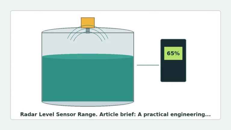
Non-contact radar level transmitters operate using the Time-of-Flight (ToF) principle. The instrument emits a high-frequency microwave signal (typically in the 26 GHz or 80 GHz range) toward the product surface. The signal reflects off the liquid and returns to the sensor. The transmitter calculates the distance based on the time interval between emission and reception:
$$D = \frac{c \times t}{2}$$
Where:
* D is the distance to the liquid surface.
* c is the speed of light.
* t is the measured time delay.
The Function of a Stilling Well
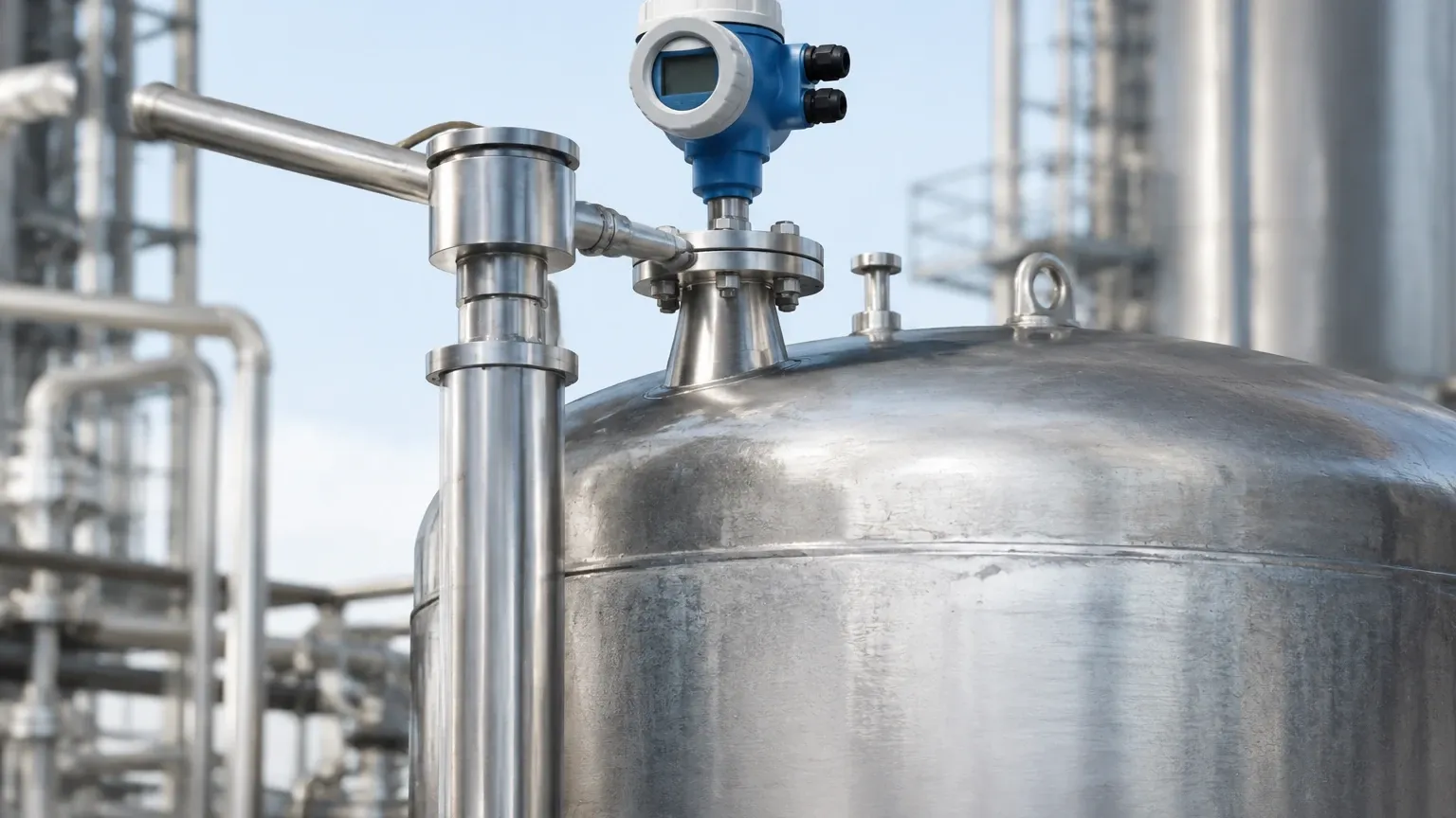
A stilling well is a vertical pipe installed inside a storage tank or process vessel, extending from the top to the bottom. In the context of Radar Level Meters, the stilling well serves three primary technical purposes:
1. Waveguide Effect: The pipe acts as a waveguide, focusing the microwave energy and preventing the beam from spreading. This significantly increases the signal-to-noise ratio (SNR), which is critical for liquids with a low dielectric constant ($\epsilon_r < 2.0$).
2. Surface Stabilization: It isolates the liquid surface from turbulence caused by agitators, mixers, or high-velocity inflows, providing a "still" surface for the radar to track.
3. Bypass of Obstructions: In tanks crowded with heating coils, ladders, or baffles, the stilling well provides a clear, unobstructed path for the radar signal, eliminating false echoes.
2. Selection Criteria for Radar and Pipe Integration
When specifying a non contact radar level transmitter with stilling well, engineers must match the radar frequency and antenna type to the pipe dimensions.
Frequency Considerations
* 26 GHz Radar: Traditionally the standard for stilling well applications. The wavelength is well-suited for standard pipe diameters (DN50 to DN200). It is less sensitive to small build-ups on the pipe wall than higher frequencies.
* 80 GHz Radar: Offers a much narrower beam angle. While 80 GHz is often used in open-tank applications to avoid obstructions, it is increasingly used in stilling wells because the narrow beam reduces interference from pipe seams and welds.
Material and Pipe Diameter
The pipe must be constructed from a conductive material (typically stainless steel or carbon steel) to act as a proper waveguide. Plastic pipes (PVC/PP) do not provide the same waveguide benefits and may lead to signal leakage.
| Feature | Recommended Specification |
| :— | :— |
| Pipe Diameter | DN50 (2") to DN250 (10") |
| Pipe Material | 316L Stainless Steel or Carbon Steel |
| Antenna Type | Horn or Planar (sized to fit the pipe ID) |
| Pressure Rating | Must match vessel flange rating (e.g., PN16, PN40) |
| Dielectric Constant | Suitable for $\epsilon_r \geq 1.4$ in stilling wells |
3. Engineering and Installation Best Practices
Proper installation is the most critical factor in the performance of a non contact radar level transmitter with stilling well. Failure to follow these guidelines often results in signal loss or "lock-on" errors where the radar tracks a fixed point in the pipe rather than the liquid.
Vent Holes and Equalization
A stilling well must have a vent hole at the very top, above the maximum liquid level. This ensures that the air pressure inside the pipe is equal to the pressure in the tank headspace. Without this, the liquid level inside the pipe will not match the level in the tank due to trapped air or vacuum effects.
Pipe Interior Smoothness
The interior of the stilling well must be as smooth as possible. Radar waves are sensitive to any physical protrusion. Engineers should ensure:
* Welded Joints: If the pipe consists of multiple sections, the internal welds must be ground flush. Any remaining weld bead can create a permanent false echo.
* Hole Deburring: Any holes drilled along the length of the pipe (for liquid equalization) must be deburred on the inside.
* Alignment: The pipe must be installed perfectly vertical (within $\pm 1^{\circ}$) to prevent the radar beam from hitting the pipe wall repeatedly, which causes signal attenuation.
Antenna Positioning
The radar antenna should be centered within the pipe. Most industrial radar level meters use a flange mounting system. It is vital to ensure the antenna does not touch the pipe wall, as this can cause a short-circuit of the microwave signal or significant near-zone interference.
4. Limitations and Application Risks
While highly effective, the use of a stilling well is not a universal solution. Engineers should be aware of the following limitations:
* Viscous and Clogging Liquids: If the process medium is highly viscous, prone to crystallization, or contains heavy solids, the stilling well can become clogged. This prevents the liquid level inside the pipe from equalizing with the tank, leading to dangerous false readings.
* Scaling and Build-up: Over time, paraffin, wax, or chemical scales can build up on the inner walls of the pipe. This narrows the effective diameter and creates parasitic reflections that degrade measurement accuracy.
* Corrosion: In corrosive environments, the pipe wall may thin or develop pits. Because the pipe acts as the waveguide, changes in the wall's conductivity or physical integrity will impact the radar signal.
5. Comparison: Stilling Well vs. Other Level Technologies
| Technology | Advantage in Stilling Well | Limitation |
| :— | :— | :— |
| Non-Contact Radar | No moving parts; high accuracy; handles high temp/pressure. | Sensitive to pipe wall condition. |
| Guided Wave Radar (GWR) | Direct contact with liquid; excellent for low $\epsilon_r$. | Probe can touch pipe wall; difficult to clean. |
| Ultrasonic Sensors | Cost-effective for water-based liquids. | Cannot be used in vacuum; affected by vapor/temp layers. |
| Displacer/Float | Simple mechanical principle. | Moving parts prone to mechanical failure/jamming. |
6. International Buyer’s Checklist for Procurement
When sourcing a non contact radar level transmitter with stilling well from an international manufacturer like Welk, B2B buyers should confirm the following technical details to ensure compatibility:
1. Process Connection: Confirm flange standards (ANSI, DIN, or JIS) and sizes. A mismatch here is the most common cause of installation delays.
2. Frequency Selection: Specify if the application involves low dielectric liquids (like LPG or LNG), which may require specific signal processing software.
3. Dead Zone (Blocking Distance): Check the instrument's dead zone. In stilling wells, the top 100 mm to 300 mm of the pipe may be unmeasurable depending on the antenna design.
4. Certifications: Ensure the device carries necessary hazardous area certifications (ATEX, IECEx) if being used in oil and gas environments.
5. OEM/ODM Customization: For large-scale projects, verify if the manufacturer can provide customized antenna extensions or high-temperature cooling fins.
7. Frequently Asked Questions (FAQ)
Q: Can I use a radar level meter in a plastic stilling well?
A: It is not recommended. Radar waves pass through plastic. Without a conductive metal wall, you lose the waveguide effect that concentrates the signal, and you may pick up false reflections from outside the pipe.
Q: How many equalization holes should the stilling well have?
A: This depends on the viscosity of the liquid and the rate of level change. Generally, two 12 mm (1/2 inch) holes every 500 mm (20 inches) is sufficient for most light liquids. Ensure they are deburred internally.
Q: Does the stilling well need to be grounded?
A: Yes. The stilling well should be electrically bonded to the tank and the radar transmitter to ensure a consistent ground plane and to prevent the buildup of static electricity, especially in explosive atmospheres.
Q: What is the maximum length for a stilling well?
A: Stilling wells can exceed 20 meters (65 feet) in large storage tanks. However, for very long runs, the verticality of the pipe and the smoothness of the internal joints become extremely critical to prevent signal loss.
By following these engineering guidelines, industrial facilities can maximize the reliability of their Radar Level Meters. The combination of non-contact sensing and stilling well stability provides a robust solution for the most challenging level measurement tasks in modern automation.
Download Non Contact Radar Level Transmitter with Stilling Well as a PDF