External Pipe Flow Meter
External Pipe Flow Meter
In modern industrial process control, the ability to measure fluid dynamics without interrupting production or compromising the integrity of the piping system is a significant operational advantage. An external pipe flow meter, primarily utilizing ultrasonic technology, allows for non-invasive measurement of liquids. By clamping sensors to the outside of a pipe, facilities can monitor flow rates in real-time without the risks associated with cutting pipes, such as leaks, pressure drops, or contamination.
This guide provides a technical overview of external flow measurement technologies, their operating principles, selection criteria, and installation best practices for B2B applications in water treatment, chemical processing, and oil and gas sectors.
Measurement Principles of External Flow Meters
External pipe flow meters are almost exclusively based on ultrasonic technology. These devices use acoustic transducers to send and receive sound waves through the pipe wall and the fluid. There are two primary methods used to calculate flow: Transit-Time and Doppler Effect.
Transit-Time Ultrasonic Principle
Transit-time meters utilize a pair of transducers that function as both transmitters and receivers. They are mounted on the outside of the pipe, either on opposite sides or the same side. The meter measures the time it takes for an ultrasonic signal to travel from one transducer to the other.
When the fluid is moving, the signal traveling upstream (against the flow) takes longer than the signal traveling downstream (with the flow). The difference in these travel times is directly proportional to the velocity of the fluid. This technology is most effective for clean liquids with low concentrations of suspended solids or entrained gases.
Doppler Effect Principle
Doppler flow meters operate by transmitting ultrasonic sound into the fluid and measuring the frequency shift of the signal reflected off moving particles or air bubbles. According to the Doppler Effect, the frequency of the reflected signal changes in proportion to the velocity of the reflectors.
Unlike transit-time meters, Doppler meters require a minimum concentration of particles or bubbles (typically at least 100 parts per million of 75-micron sized particles) to function correctly. This makes them ideal for wastewater, slurries, and aerated liquids.
Comparison of External Flow Measurement Technologies
Choosing the correct external pipe flow meter depends heavily on the characteristics of the fluid and the pipe material. The following table outlines the key differences between the two primary ultrasonic methods.
| Feature | Transit-Time Ultrasonic | Doppler Ultrasonic |
| :— | :— | :— |
| Fluid Type | Clean liquids (water, oils, chemicals) | Dirty liquids (sewage, slurries, aerated fluids) |
| Particle Concentration | < 1% to 2% suspended solids | > 100 ppm of particles/bubbles |
| Accuracy | High (typically ±0.5% to ±2% of rate) | Moderate (typically ±2% to ±5% of full scale) |
| Pipe Sizes | 10 mm to over 6,000 mm | 12.5 mm to over 6,000 mm |
| Application Focus | Potable water, HVAC, pure chemicals | Wastewater treatment, mining, dredging |
Key Selection Criteria for Industrial Applications
When evaluating an external pipe flow meter for a specific project, engineers must confirm several technical parameters to ensure reliable performance. These factors influence the signal strength and the overall accuracy of the measurement.
1. Pipe Material and Condition
Ultrasonic signals must pass through the pipe wall. Homogeneous materials like carbon steel, stainless steel, copper, and most plastics (PVC, PE) are excellent conductors of sound. However, pipes with internal liners (such as cement or rubber) or those heavily corroded on the inside can attenuate the signal, leading to measurement errors. It is essential to verify the pipe wall thickness and the presence of any liners before selection.
2. Fluid Characteristics
As noted in the principles section, the presence of solids or bubbles dictates whether a transit-time or Doppler meter is required. Additionally, the fluid's temperature affects the speed of sound, which the meter must compensate for. Most high-quality external meters include temperature compensation algorithms or external temperature sensors for this purpose.
3. Flow Profile and Straight Pipe Runs
For accurate measurement, the fluid flow must be fully developed and laminar. Obstructions like elbows, valves, pumps, and reducers create turbulence that interferes with ultrasonic signals.
* Upstream: A minimum of 10 pipe diameters (10D) of straight pipe is generally required.
* Downstream: A minimum of 5 pipe diameters (5D) of straight pipe is recommended.
4. Environmental Rating
In industries like oil and gas or chemical processing, the meter housing and transducers must meet specific ingress protection (IP) ratings (e.g., IP67 or IP68) and hazardous area certifications (ATEX/IECEx) if installed in explosive atmospheres.
Installation Considerations and Best Practices
Proper installation is the most critical factor in the success of an external pipe flow meter. Unlike inline meters, the performance of a clamp-on meter is entirely dependent on how well the transducers are coupled to the pipe.
Surface Preparation
The pipe surface where the transducers will be mounted must be cleaned of rust, loose paint, and scale. For optimal signal transmission, the surface should be ground down to bare metal or smooth plastic. A coupling compound (acoustic gel or grease) is then applied between the transducer face and the pipe to eliminate air gaps.
Mounting Configurations
There are three common mounting methods for external transducers:
1. V-Method: The transducers are mounted on the same side of the pipe. The signal bounces off the opposite wall once. This is the standard method for pipes ranging from 25 mm to 400 mm (1" to 16").
2. Z-Method: The transducers are mounted on opposite sides of the pipe. The signal travels directly across the fluid. This is used for large pipes or when the fluid is highly attenuative.
3. W-Method: The signal bounces three times before reaching the receiver. This is used for very small pipes (under 25 mm) to increase the signal path length and improve resolution.
Transducer Alignment
Precise spacing between transducers is calculated by the meter's transmitter based on the entered pipe parameters (diameter, wall thickness, material). Even a few millimeters of misalignment can result in significant signal loss.
Integration with Level Measurement Systems
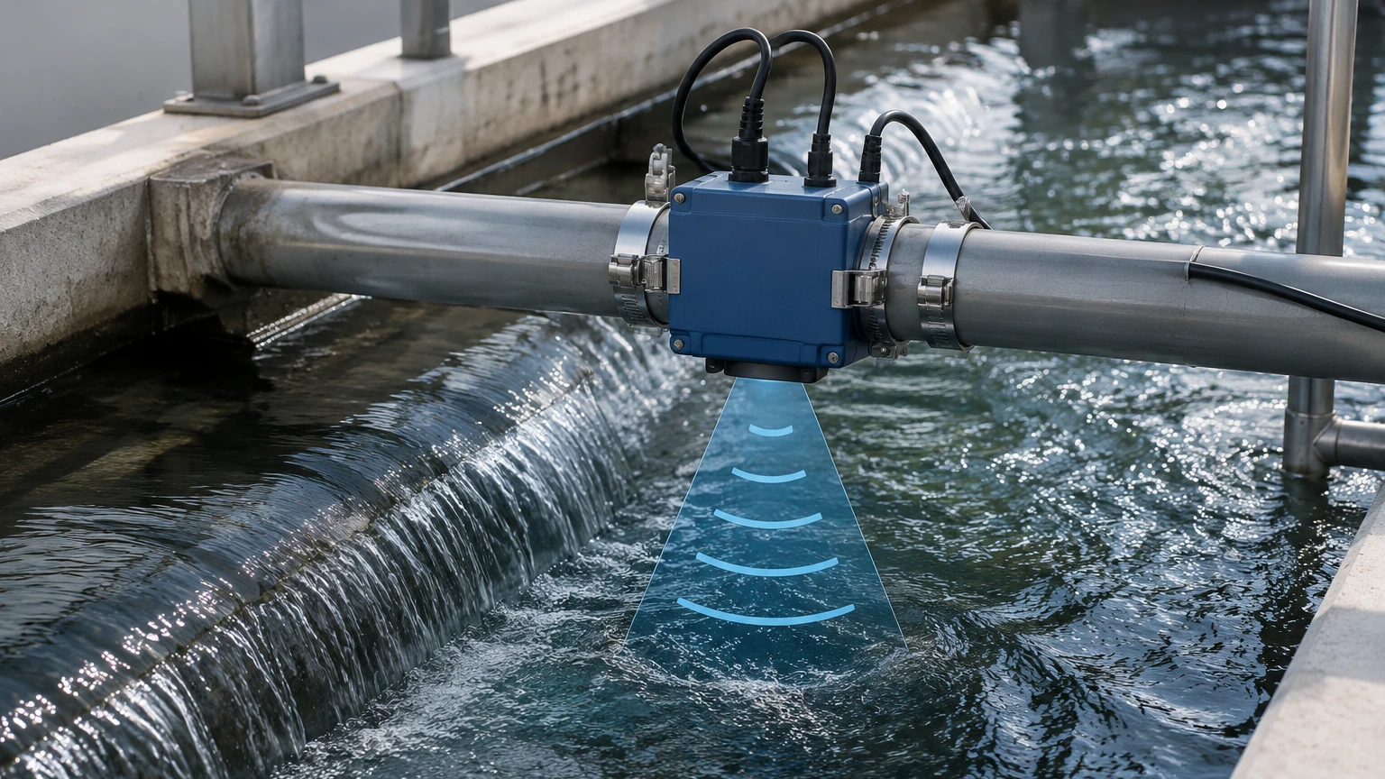
In many industrial automation scenarios, flow measurement is used in conjunction with level measurement to provide a complete picture of process efficiency. For instance, in water treatment plants, an external pipe flow meter monitors the discharge rate while a radar or ultrasonic level sensor monitors the tank inventory.
As a professional manufacturer of industrial instrumentation, Welk provides a comprehensive range of solutions for these applications. While flow meters track the movement of media, our level measurement instruments—including radar level meters and hydrostatic transmitters—ensure that storage and processing volumes are managed accurately. For more information on integrating these technologies, you can visit the Main Page to review product options and application support.
Common Risks and Limitations
While external pipe flow meters offer numerous benefits, they are not universal solutions. Engineers should be aware of the following limitations:
* Signal Attenuation: Highly viscous liquids or fluids with extremely high concentrations of solids can absorb ultrasonic energy, preventing the signal from reaching the receiver.
* Pipe Wall Interference: If the pipe wall is not perfectly bonded to an internal liner, an air gap may exist. Since sound travels poorly through air, the meter will fail to receive a signal.
* Scaling and Fouling: Internal buildup (scaling) changes the effective internal diameter of the pipe. If the meter is not updated with the new diameter, the flow rate calculation (which relies on the cross-sectional area) will be incorrect.
Frequently Asked Questions (FAQ)
Q: Can external flow meters measure gas flow?
A: Most standard clamp-on meters are designed for liquids. While specialized high-pressure gas ultrasonic meters exist, they are significantly more complex and expensive due to the low density of gas, which makes acoustic coupling difficult.
Q: How often does the coupling gel need to be replaced?
A: In permanent installations, high-quality silicone-based coupling grease can last for several years. However, in high-temperature applications or outdoor environments with extreme weather, it is recommended to inspect the coupling every 12 to 24 months.
Q: Do these meters work on plastic pipes?
A: Yes, ultrasonic signals travel very well through most plastics like PVC, HDPE, and PVDF. They are often easier to measure than metal pipes because they do not suffer from the same corrosion issues.
Q: What is the minimum flow velocity required?
A: Most transit-time meters can measure velocities as low as 0.01 m/s (0.03 ft/s), making them excellent for detecting leaks or very slow process flows.
Conclusion
The external pipe flow meter is a versatile and cost-effective tool for modern industrial environments. By eliminating the need for pipe modifications, these devices reduce installation costs and prevent process downtime. When selected based on accurate pipe and fluid data and installed with attention to surface preparation and alignment, they provide reliable data essential for process optimization and resource management. For those looking to enhance their industrial automation with high-precision level and flow instrumentation, consulting with experienced manufacturers ensures that the chosen technology aligns with specific application requirements.