How Do Flowmeters Work
How Do Flowmeters Work
In the realm of industrial process control, the ability to quantify the movement of liquids, gases, and vapors is as critical as measuring the volume stored within a tank. Flowmeters serve as the sensory organs of a piping system, providing real-time data necessary for billing, dosing, safety, and efficiency. Understanding how do flowmeters work requires a dive into various physical principles, ranging from classical mechanics and electromagnetism to advanced acoustics.
Selecting the right instrument involves more than just matching a pipe size; it requires an alignment between the fluid's physical properties and the measurement technology's underlying physics. This guide provides an engineering-focused overview of flow measurement principles, selection criteria, and practical installation considerations.
Core Principles of Flow Measurement
Before exploring specific technologies, it is essential to distinguish between the two primary types of flow measurement: volumetric and mass flow. Volumetric flow measures the space occupied by the fluid (e.g., cubic meters per hour, m³/h), while mass flow measures the actual weight of the fluid moving through the system (e.g., kilograms per hour, kg/h).
Velocity-Based Measurement
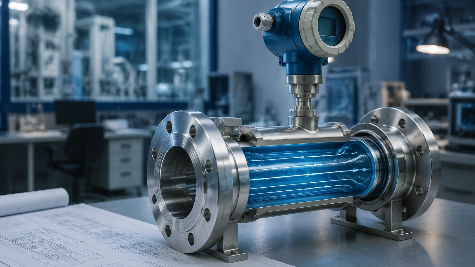
Most industrial flowmeters determine flow by measuring the velocity of the fluid within a known cross-sectional area ($Q = A \times v$). If the velocity ($v$) and the area ($A$) are known, the volumetric flow rate ($Q$) can be calculated. Technologies using this principle include turbine, vortex, and ultrasonic meters.
Differential Pressure (DP)
Based on Bernoulli’s principle, DP meters create a constriction in the pipe. As fluid passes through the constriction, its velocity increases and its pressure decreases. The difference in pressure between the upstream and downstream sides is proportional to the square of the flow rate. Common examples include orifice plates, Venturi tubes, and Pitot tubes.
Electromagnetic Induction
Following Faraday’s Law, electromagnetic flowmeters (magmeters) operate on the principle that a conductor (a conductive liquid) moving through a magnetic field generates a voltage. This voltage is directly proportional to the velocity of the liquid.
Acoustic and Frequency Principles
Ultrasonic meters use sound waves to calculate velocity, while vortex meters measure the frequency of pressure oscillations (vortices) shed by a "bluff body" placed in the flow stream.
How Do Flowmeters Work: A Detailed Technology Breakdown
To answer the question of how do flowmeters work in a practical setting, we must examine the specific mechanics of the most common industrial types.
1. Electromagnetic Flowmeters (Magmeters)
Magmeters are the workhorses of the water treatment and chemical industries. They consist of a non-conductive liner and two electromagnetic coils. When the coils are energized, they create a magnetic field across the pipe. As a conductive liquid (like water or acids) flows through this field, it generates a voltage detected by electrodes.
* Requirement: The fluid must have a minimum conductivity, typically $>5 \mu S/cm$.
* Advantage: No moving parts and no pressure drop.
2. Ultrasonic Flowmeters
These instruments are categorized into two types: Transit-Time and Doppler.
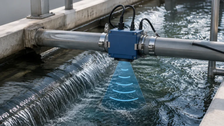
* Transit-Time: Two transducers act as both transmitters and receivers. They send ultrasonic pulses back and forth. Pulses traveling with the flow move faster than those traveling against it. The time difference is used to calculate velocity. These are best for clean liquids.
* Doppler: These reflect sound waves off bubbles or particles in the fluid. The frequency shift (Doppler effect) between the transmitted and received signal indicates the flow speed. These are ideal for slurries or aerated liquids.
3. Vortex Flowmeters
Vortex meters utilize the von Kármán effect. A "bluff body" (a vertical bar) is placed in the flow path. As fluid hits this bar, it cannot pass through it and must go around, creating alternating vortices (swirls) downstream. A sensor detects the frequency of these vortices, which is linearly proportional to the flow velocity. These are highly valued for steam measurement.
4. Turbine Flowmeters
These contain a multi-bladed rotor mounted on bearings. As fluid passes through, it pushes the blades, causing the rotor to spin. The rotational speed is proportional to the flow velocity. A pickup coil outside the pipe counts the passing of the blade tips to determine the flow rate. While highly accurate, they are susceptible to wear and damage from debris.
5. Coriolis Mass Flowmeters
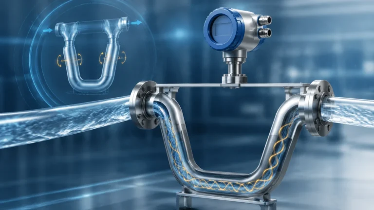
Unlike the previous types, Coriolis meters measure mass directly. They consist of one or more vibrating tubes. As fluid flows through the vibrating tube, the inertia causes the tube to twist or shift in phase. This displacement is directly proportional to the mass flow rate. These are the most accurate and expensive meters, used extensively in oil and gas for custody transfer.
Practical Selection Table
Choosing the correct meter depends on the media, required accuracy, and budget. For a broader range of industrial instrumentation, including level measurement solutions that often complement flow monitoring, you may Review product options and application support on our main site.
| Technology | Suitable Media | Accuracy (Typical) | Pressure Drop | Moving Parts |
| :— | :— | :— | :— | :— |
| Electromagnetic | Conductive Liquids | ±0.5% | None | No |
| Ultrasonic | Clean/Dirty Liquids | ±1.0% | None | No |
| Vortex | Steam, Gas, Liquids | ±1.0% | Medium | No |
| Turbine | Clean Liquids, Gas | ±0.25% | High | Yes |
| Coriolis | Liquids, Slurries, Gas | ±0.1% | Medium | No |
| Differential Pressure | Liquids, Gas, Steam | ±1.0% to 2.0% | High | No |
Installation Considerations
Even the most expensive flowmeter will fail to provide accurate data if installed incorrectly. Engineers must adhere to the following guidelines:
1. Straight Pipe Runs: Most meters (especially DP, Turbine, and Vortex) require a specific length of straight pipe upstream and downstream to ensure a stable, non-turbulent flow profile. A common rule of thumb is 10 diameters (10D) upstream and 5 diameters (5D) downstream, though this varies by technology.
2. Orientation: For liquid applications, the pipe must remain full. Installing a meter in a vertical pipe with upward flow is often preferred to ensure the pipe is always flooded. Horizontal installations should avoid placing electrodes at the very top or bottom of the pipe to prevent interference from air bubbles or sediment.
3. Grounding: Electromagnetic meters are sensitive to electrical noise. Proper grounding to the fluid and the pipe is essential to prevent signal interference.
4. Avoid Cavitation: Ensure the system pressure remains high enough to prevent the fluid from vaporizing as it passes through the meter, which can damage the instrument and cause massive errors.
Limitations and Common Risks
While understanding how do flowmeters work is the first step, recognizing their limitations prevents operational failure:
* Viscosity Sensitivity: Turbine and DP meters are highly sensitive to changes in fluid viscosity. If a fluid thickens due to temperature drops, these meters may become significantly less accurate.
* Conductivity Limits: Magmeters cannot measure hydrocarbons (like oil or diesel) or deionized water because these fluids do not conduct electricity.
* Mechanical Wear: Any meter with moving parts (Turbine, Positive Displacement) will eventually experience bearing wear, requiring recalibration or replacement.
* Signal Interference: Ultrasonic meters can be affected by external vibrations or high-frequency noise from nearby pumps or control valves.
Integration with Level Measurement
In many industrial applications, flow and level measurement are used in tandem. For example, in a water treatment plant, an ultrasonic level sensor might monitor the height of water in a tank, while an electromagnetic flowmeter monitors the rate at which that water is discharged. Welk provides a comprehensive range of level instruments—including radar, ultrasonic, and hydrostatic transmitters—that integrate seamlessly with flow control systems to provide a complete picture of process dynamics.
Frequently Asked Questions (FAQs)
Q: Can one flowmeter measure both liquid and gas?
A: Some technologies, like Vortex and Coriolis, are versatile enough to measure both. However, the calibration and physical sizing for a gas application are usually very different from a liquid application.
Q: Why is my ultrasonic flowmeter giving inconsistent readings?
A: This is often due to "signal attenuation." If the liquid contains too many solids (for transit-time) or too few (for Doppler), the signal cannot pass through or reflect properly. Also, check for air bubbles or poor transducer coupling to the pipe.
Q: How often should a flowmeter be recalibrated?
A: For non-critical applications, every 2-3 years is standard. For custody transfer (where money changes hands based on the reading), annual or even quarterly calibration may be legally required.
Q: What is the "Turndown Ratio"?
A: This is the range over which a meter can measure accurately. A 10:1 turndown ratio means if the maximum flow is 100 m³/h, the meter can accurately measure down to 10 m³/h.
Conclusion
Understanding how do flowmeters work is essential for any engineer involved in industrial automation. By matching the physical principle—whether it be electromagnetic, acoustic, or mechanical—to the specific needs of the application, facilities can ensure long-term reliability and precision. For those looking to optimize their entire fluid management system, exploring high-quality Main Page resources for both level and flow instrumentation is the best path forward to achieving operational excellence.