Radar Level Transmitter Parts
Radar Level Transmitter Parts: A Technical Guide to Components and Selection
In modern industrial process automation, the accuracy of level measurement directly impacts operational safety, inventory management, and process efficiency. Among the various technologies available, Radar Level Meters have emerged as a preferred solution for non-contact measurement in challenging environments. Understanding the specific radar level transmitter parts and their functions is essential for engineers and procurement specialists to ensure the longevity and reliability of their instrumentation.
This guide examines the fundamental principles of radar measurement, details the critical components of a transmitter, and provides practical selection criteria for industrial applications.
Measurement Principles of Radar Technology
Before detailing the individual radar level transmitter parts, it is necessary to understand how these devices function. Radar level measurement is based on the travel time of electromagnetic waves. There are two primary methods used in industrial radar transmitters:
Time of Flight (ToF) / Pulse Radar
Pulse radar emits short microwave pulses toward the surface of the medium. These pulses are reflected back to the antenna. The transmitter measures the time elapsed between emission and reception. Since the speed of light is constant, the distance to the product surface is calculated using the formula:
*Distance = (Speed of Light × Travel Time) / 2*.
Frequency Modulated Continuous Wave (FMCW)
FMCW radar transmits a continuous signal with a constantly changing frequency. When the reflected signal is received, it is compared to the signal being emitted at 그 moment. The frequency difference is directly proportional to the distance. FMCW is generally considered more accurate for complex applications because it provides better signal-to-noise ratios.
In both methods, the frequency of the radar (typically 6GHz, 26GHz, or 80GHz) dictates the beam angle and the ability of the signal to penetrate dust, steam, or foam. Higher frequencies, such as 80GHz, allow for smaller antenna sizes and narrower beam angles, reducing interference from tank internal structures.
Core Radar Level Transmitter Parts and Functions
A radar level transmitter is a sophisticated assembly of electronic and mechanical components. Each part must be selected based on the specific chemical and physical properties of the process environment.
1. The Electronic Housing
The housing protects the transmitter’s internal circuitry from environmental factors such as moisture, corrosive vapors, and mechanical impact.
* Materials: Typically constructed from powder-coated aluminum or 316L stainless steel for highly corrosive environments.
* Ingress Protection: Standard industrial housings usually meet IP66 or IP67 ratings, ensuring they are dust-tight and protected against powerful water jets.
* Compartments: High-quality transmitters often feature dual-compartment housings, separating the wiring terminals from the sensitive electronics to prevent contamination during installation.
2. The Antenna (Signal Transceiver)
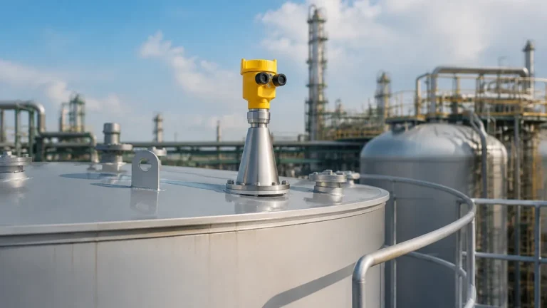
The antenna is perhaps the most critical of all radar level transmitter parts. It is responsible for focusing the radar beam and capturing the return echo.
* Horn Antenna: Common in large tanks and for measuring liquids with low dielectric constants. They are usually made of stainless steel.
* Lens Antenna: Often used with 80GHz high-frequency radar. The lens (typically PTFE or PFA) protects the electronics and allows for a flush-mount design, which is ideal for preventing material buildup.
* Rod Antenna: Best suited for small openings or corrosive liquids. These are often fully encapsulated in PTFE.
* Parabolic Antenna: Used for long-range measurements (up to 70m or 100m) in large silos containing solids or ores.
3. The Signal Processing Unit (PCBA)
This is the "brain" of the transmitter. The printed circuit board assembly (PCBA) contains the microwave oscillator, the receiver, and the microprocessor. It filters out "false echoes" caused by agitators, ladders, or tank walls using advanced algorithms (often referred to as echo mapping or false signal suppression).
4. Process Connection
This part secures the transmitter to the vessel. The choice of connection depends on the pressure and temperature of the tank.
* Threaded Connections: Common for smaller sensors and low-pressure applications.
* Flanged Connections: Standard for most industrial vessels, available in various sizes (DN50 to DN200) and pressure ratings.
* Sanitary Fittings: Used in food, beverage, and pharmaceutical industries to ensure no bacterial growth occurs at the connection point.
5. Display and Interface Module
Most modern transmitters include a plug-in LCD module that allows for local configuration and real-time monitoring. These modules often support multiple languages and display the echo curve, which is invaluable for troubleshooting.
Selection Table: Matching Parts to Applications
Choosing the correct configuration of radar level transmitter parts requires balancing performance with cost. Use the following table as a general engineering reference:
| Application Environment | Recommended Antenna Type | Housing Material | Frequency Recommendation |
| :— | :— | :— | :— |
| Corrosive Chemicals | PTFE-sealed Lens/Rod | 316L Stainless Steel | 80 GHz |
| Large Grain Silos | Parabolic or Large Horn | Aluminum | 26 GHz / 80 GHz |
| High-Pressure Steam | Horn with Glass Seal | Aluminum | 26 GHz |
| Small Process Tanks | Small Lens Antenna | Aluminum | 80 GHz |
| Water Treatment | Standard Horn | Aluminum | 26 GHz |
Installation Considerations and Best Practices
Even the highest quality radar level transmitter will fail to provide accurate data if installed incorrectly. Engineers should observe the following constraints:
1. Nozzle Height and Diameter: The antenna should extend slightly beyond the mounting nozzle to prevent the signal from reflecting off the nozzle edges. If the nozzle is long, a higher frequency radar (80GHz) is preferred due to its narrow beam.
2. Obstruction Avoidance: The radar beam should not intersect with internal tank structures like heating coils, agitators, or ladders. A minimum distance of 200mm to 500mm from the tank wall is usually recommended to avoid interference.
3. Inlet Positioning: Never install the transmitter directly above the product inlet. The turbulence and falling material will cause significant signal noise.
4. Polarization: The orientation of the transmitter can affect signal strength. Rotating the housing can sometimes help bypass internal obstructions.
Limitations and Application Risks
While Radar Level Meters are highly versatile, certain conditions can impact their performance:
* Dielectric Constant (εr): Materials with very low dielectric constants (like liquid gases or certain oils) reflect less energy. In these cases, specialized high-sensitivity electronics or guided wave radar may be required.
* Heavy Foam: Dense, thick foam can absorb the radar signal entirely. If foam is a constant factor, a low-frequency radar (6GHz) might penetrate it better, though mechanical solutions like stilling wells are often more effective.
* Turbulence: Extreme surface agitation can scatter the radar signal. Signal processing software can compensate for this to an extent, but a stilling well is the most reliable engineering fix for heavy turbulence.
Maintenance and Troubleshooting FAQ
Q: Can I replace individual radar level transmitter parts if they fail?
A: Yes. Most professional manufacturers design transmitters modularly. The display module, the electronic insert, and the antenna assembly can often be replaced without discarding the entire unit.
Q: How do I clean a lens antenna if buildup occurs?
A: For non-contact radar, a damp cloth is usually sufficient. If the medium is prone to crystallization, some transmitters can be equipped with a compressed air purging connection to keep the antenna face clean automatically.
Q: Why is my transmitter showing a "Full Tank" error when it is empty?
A: This is often caused by a "ringing" effect or a strong reflection from the mounting nozzle. Ensure the antenna is clean and check if the false echo suppression (echo mapping) needs to be recalibrated.
Conclusion for International Buyers
When sourcing equipment for industrial level measurement, it is vital to provide the manufacturer with a complete process profile. This includes the medium name, dielectric constant, operating temperature, process pressure, and tank dimensions.
By understanding the various radar level transmitter parts—from the robust 316L housing to the precision-engineered 80GHz lens antenna—procurement teams can select solutions that minimize maintenance and maximize uptime. For specialized applications, consulting with a manufacturer that offers customized OEM/ODM services ensures that the instrumentation is perfectly tailored to the specific demands of the facility.