Open Path Radar Level Transmitter
Open Path Radar Level Transmitter: Engineering Selection and Application Guide
In the landscape of industrial automation, the demand for non-contact, high-precision measurement has led to the widespread adoption of radar technology. An open path radar level transmitter represents a specific application of non-contact radar designed to measure liquid or solid levels in environments where the sensor signal travels through an open atmosphere or non-pressurized space. These instruments are essential for water treatment, open-channel flow monitoring, large-scale chemical storage, and mining operations.
As a professional manufacturer, Welk provides advanced Radar Level Meters that leverage high-frequency electromagnetic waves to deliver reliable data even in challenging environmental conditions. Understanding the physics, selection criteria, and installation constraints is critical for engineering teams tasked with integrating these sensors into industrial control systems.
1. Measurement Principles of Open Path Radar
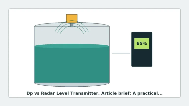
Open path radar level transmitters operate on the principle of Time of Flight (ToF). The device emits high-frequency electromagnetic pulses (typically in the microwave spectrum) toward the material surface. When these waves encounter a change in the dielectric constant (the boundary between air and the medium), a portion of the energy is reflected back to the sensor antenna.
Frequency Modulated Continuous Wave (FMCW)
Modern high-precision radar transmitters often utilize FMCW technology. Instead of sending a single pulse, the transmitter emits a continuous signal with a frequency that varies over time (a linear ramp). The difference in frequency between the emitted signal and the reflected echo is proportional to the distance. This method allows for significantly higher resolution and signal-to-noise ratios compared to traditional pulse radar, making it ideal for the long distances often encountered in open-path applications.
Signal Propagation and Dielectric Constants
The reliability of the reflection depends heavily on the dielectric constant (εr) of the target medium. Water has a high dielectric constant (εr ≈ 80), providing a very strong reflection. Conversely, hydrocarbons, oils, and certain dry solids have low dielectric constants (εr < 2.0), which absorb more energy and reflect less. In open-path scenarios, where signal dissipation can occur over long distances, selecting a transmitter with sufficient sensitivity and the correct frequency is paramount.
2. Frequency Selection: 26GHz vs. 80GHz
The frequency of the radar signal dictates the beam angle and the instrument's ability to handle obstacles.
* 26GHz Radar: Historically the standard for industrial level measurement. It features a wider beam angle, which can be advantageous in applications with heavy foam or turbulence, as the broader signal is more likely to capture a return from an uneven surface. However, it requires larger antennas to maintain signal focus.
* 80GHz Radar: The current state-of-the-art for open path radar level transmitters. Due to the shorter wavelength, 80GHz units can achieve very narrow beam angles (as low as 3°). This allows the signal to bypass internal tank structures, narrow flumes, or nearby walls without generating false echoes. 80GHz is also superior for measuring materials with low dielectric constants due to its higher energy density.
3. Selection Criteria for Industrial Applications
Selecting the right open path radar level transmitter requires a detailed analysis of the process environment. The following table provides a generalized comparison for selection purposes:
| Feature | 26 GHz Pulse/FMCW | 80 GHz FMCW |
| :— | :— | :— |
| Typical Beam Angle | 8° to 20° | 3° to 8° |
| Maximum Range | 30m (98 ft) | 120m (393 ft) |
| Measurement Accuracy | ±3mm to ±5mm | ±1mm to ±2mm |
| Antenna Type | Horn, Parabolic | Lens (flush-mounted) |
| Process Connection | Threaded or Flanged | Threaded, Flanged, or Bracket |
| Best Use Case | Large silos, turbulent liquids | Narrow channels, high-precision tanks |
Antenna Considerations
For open path applications, the antenna design is a primary factor in performance:
* Horn Antennas: Common for 26GHz units, suitable for standard liquid measurement.
* Lens Antennas: Often used in 80GHz units; they are flush-mounted and typically made of PTFE or PEEK, making them resistant to condensation and chemical vapors.
* Parabolic Antennas: Used for extremely long-range measurements (up to 100m+) in large open-air stockpiles or deep reservoirs.
4. Installation Constraints and Engineering Best Practices
Even the most advanced radar level meters will fail if installed incorrectly. Open path environments present unique challenges such as wind, solar heating, and structural interference.
Avoiding the "Dead Zone"
Every radar transmitter has a "blocking distance" or dead zone directly beneath the antenna (typically 0.1m to 0.5m / 4" to 20"). Measurement is not possible within this range. Engineers must ensure the maximum expected level of the medium never enters this zone.
Beam Path Clearance
The radar beam expands as it travels. For an open path radar level transmitter, the path must be clear of ladders, pipes, or structural beams.
* The 1/6th Rule: A general guideline for mounting is to place the sensor at a distance from the wall equal to 1/6th of the total height/depth of the vessel or channel to avoid side-wall interference.
* Obstacle Mapping: High-quality transmitters allow for "False Echo Suppression," where the software is trained to ignore reflections from fixed internal structures. However, it is always better to provide a clear line of sight.
Environmental Protection
In outdoor open-path applications, the sensor is exposed to the elements.
* Sun Shields: Direct sunlight can cause the internal electronics to overheat, leading to thermal drift. A stainless steel or plastic sun shield is recommended.
* Condensation and Rain: While radar waves pass through light rain, heavy condensation on the antenna lens can attenuate the signal. Selecting a lens antenna with a convex shape allows droplets to run off, maintaining signal integrity.

5. Application Risks and Technology Limitations
While radar is highly versatile, it is not a universal solution. Engineers must be aware of the following limitations:
1. Heavy Foam: Extremely thick, dense foam (like shaving cream) can absorb the radar signal entirely, resulting in a "loss of echo." In these cases, a guided wave radar or a different frequency may be required.
2. Vacuum and High Pressure: While not an issue for "open path" atmospheric applications, extreme pressure changes can affect the speed of the signal slightly, though radar is generally much more stable than ultrasonic sensors in this regard.
3. Extremely Low Dielectric Solids: Materials like plastic pellets or very dry wood chips may require a high-gain parabolic antenna or an 80GHz transmitter to ensure the reflected signal is strong enough to be detected above the noise floor.
4. Signal Interference: In areas with multiple radar units, frequency hopping or specific channel settings may be necessary to prevent cross-talk, although this is rare with modern encoded signals.
6. Buyer’s Checklist: Confirming Specifications with Manufacturers
When sourcing an open path radar level transmitter from an international manufacturer like Welk, B2B buyers should confirm the following technical details to ensure compatibility and longevity:
* Output Protocol: Does the facility require 4-20mA (Analog), HART, Modbus RS485, or Profibus?
* Power Supply: Is 24V DC (two-wire) or 220V AC (four-wire) available at the installation site?
* Explosion-Proof Ratings: Does the environment require ATEX, IECEx, or Ex-d ratings for hazardous dust or gas?
* Process Temperature and Pressure: Even in open path applications, the flange or mounting point may be exposed to process heat.
* Material Compatibility: Ensure the wetted parts (antennas and seals) are compatible with the chemical vapors present (e.g., 316L Stainless Steel, PTFE, or Viton).
7. Frequently Asked Questions (FAQ)
Q: Can radar measure through a plastic tank lid?
A: Yes. Since plastic has a low dielectric constant, radar signals can often penetrate plastic or fiberglass covers. This allows for the sensor to be mounted outside the tank, protected from corrosive contents. However, this will result in some signal attenuation.
Q: How does radar compare to ultrasonic level sensors for open paths?
A: Radar is superior in environments with wind, temperature fluctuations, steam, or dust. Ultrasonic sensors rely on sound waves, which are affected by air density and movement. Radar uses electromagnetic waves, which are unaffected by air conditions.
Q: What maintenance is required for an open path radar level transmitter?
A: Radar units are generally low-maintenance due to the lack of moving parts. The primary task is periodically checking the antenna for buildup of material or heavy crystallization, which can be mitigated by using air purge connections or protective covers.
Q: Is 80GHz always better than 26GHz?
A: Not necessarily. While 80GHz offers better precision and smaller beam angles, 26GHz is often more cost-effective for simple, large-scale applications where high precision (±1mm) is not required and the environment is relatively clear of obstacles.
By following these engineering principles and selection guidelines, industrial operators can implement radar technology that provides years of accurate, maintenance-free level measurement. For specific project requirements or custom OEM solutions, consulting with a specialized manufacturer ensures the hardware is matched to the unique constraints of the application.