Rheonik Coriolis Mass Flow Sensors
Rheonik Coriolis Mass Flow Sensors
In the landscape of industrial process control, the precision of mass flow measurement is a critical factor for ensuring product quality, safety, and economic efficiency. Rheonik Coriolis mass flow sensors have established a specialized niche within this field, particularly in applications involving extreme pressures and temperatures. Unlike volumetric flow meters, which require compensation for temperature and pressure changes, Coriolis meters provide a direct measurement of mass flow, making them indispensable for complex chemical, oil, and gas processes.
This guide explores the engineering principles, selection criteria, and installation requirements for Rheonik Coriolis mass flow sensors, providing a technical reference for engineers tasked with optimizing fluid handling systems.
Understanding the Coriolis Measurement Principle
The fundamental principle behind Rheonik Coriolis mass flow sensors is the Coriolis effect, which describes the inertial force acting on an object in motion within a rotating frame of reference. In a flow meter, this rotation is replaced by the controlled oscillation of measuring tubes.
The Omega Tube Design
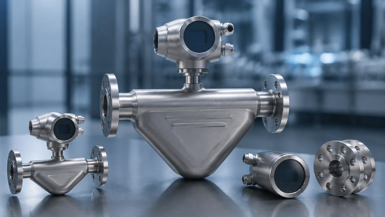
Rheonik is recognized for its unique "Omega" shaped tube geometry. While many Coriolis meters use U-shaped or straight tubes, the Omega design offers specific mechanical advantages. The sensor consists of two parallel tubes shaped like the Greek letter Omega ($\Omega$). An electromagnetic drive coil causes these tubes to vibrate at their natural resonant frequency, moving toward and away from each other like a tuning fork.
Mass Flow Detection
When a fluid (liquid or gas) flows through these vibrating tubes, it is subjected to Coriolis forces. As the fluid moves toward the center of the oscillation (the bend of the Omega), it resists the upward motion of the tube, causing a slight lag. As the fluid moves away from the center, it resists the downward motion, causing a slight lead.
This results in a twisting motion or a "phase shift" between the inlet and outlet sides of the tubes. High-precision electro-dynamic pick-up sensors located on the tubes detect this phase shift. The time difference (measured in microseconds) between the sensors is directly proportional to the mass flow rate. Because mass is an intrinsic property that does not change with temperature or pressure, the measurement remains accurate regardless of fluid density variations.
Density and Temperature Measurement
In addition to mass flow, Rheonik sensors measure the resonant frequency of the tubes. Since the frequency of vibration depends on the total mass of the tubes (tube mass + fluid mass), the meter can calculate the fluid density in real-time. Furthermore, integrated PT100 or PT1000 temperature sensors monitor the tube temperature to compensate for changes in the metal's elasticity and provide an auxiliary process temperature output.
Key Features of Rheonik Coriolis Mass Flow Sensors
Rheonik sensors are engineered for environments where standard Coriolis meters might fail. Their design focus is on durability and performance under high-stress conditions.
1. High-Pressure Capability: One of the standout features of the Rheonik RHM series is the ability to handle extreme pressures. Certain models are rated for operation up to 1,000 bar (14,500 psi) and even higher for specialized applications like hydrogen refueling stations.
2. Wide Temperature Range: These sensors can operate in cryogenic conditions as low as -200°C and high-temperature processes up to +400°C. This makes them suitable for everything from liquid nitrogen to hot thermal oils.
3. Torsion Rod Technology: Rheonik utilizes a patented torsion rod design to support the measuring tubes. This construction decouples the measuring element from external pipe vibrations and stresses, which is a common source of error in Coriolis measurement.
4. Material Versatility: Sensors are available in a variety of wetted materials, including 316L Stainless Steel, Hastelloy C22, Monel, and Tantalum, ensuring compatibility with corrosive or abrasive media.
Technical Selection and Specification Table
Selecting the correct Rheonik sensor requires matching the process flow rate, pressure, and temperature to the appropriate RHM model. Below is a general reference table for common sensor sizes.
| Model Series | Flow Range (Min – Max) | Typical Line Size | Max Pressure (Standard) | Accuracy (Liquid) |
| :— | :— | :— | :— | :— |
| RHM 015 | 0.004 – 0.6 kg/min | 1/4" to 1/2" | 450 bar | ±0.10% to 0.20% |
| RHM 03 | 0.05 – 5 kg/min | 1/4" to 1/2" | 450 bar | ±0.10% to 0.20% |
| RHM 08 | 0.5 – 50 kg/min | 1/2" to 1" | 350 bar | ±0.10% to 0.15% |
| RHM 20 | 5 – 300 kg/min | 1" to 2" | 300 bar | ±0.10% to 0.15% |
| RHM 40 | 10 – 1,500 kg/min | 2" to 3" | 200 bar | ±0.10% to 0.15% |
| RHM 160 | 100 – 16,000 kg/min | 8" to 12" | 100 bar | ±0.10% to 0.15% |
*Note: Flow ranges and pressure ratings vary significantly based on tube wall thickness and material selection. Always consult the specific manufacturer data sheet for final engineering.*
Installation Best Practices for Industrial Applications
To maintain the high accuracy of Rheonik Coriolis mass flow sensors, proper installation is paramount. Although the torsion rod design minimizes external interference, the following guidelines should be followed:
Orientation
* Liquid Service: The sensor should ideally be installed in a "tubes down" orientation (flag position) or in a vertical line with upward flow. This ensures the tubes remain full of liquid and prevents air bubbles from becoming trapped, which can cause measurement noise.
* Gas Service: For gas applications, the sensor should be installed with "tubes up." This allows any condensed liquids to drain out of the measuring tubes, preventing slugs of liquid from disrupting the oscillation.
Mechanical Support and Vibration
Coriolis meters are sensitive to vibrations that occur near their resonant frequency. While Rheonik's design is robust, it is best practice to support the piping on both sides of the meter using heavy-duty brackets. The meter itself should not be used to support the weight of the surrounding pipework. Flexible connectors are generally not recommended unless the application involves extreme mechanical vibration from pumps or compressors.
Zeroing the Meter
After installation and once the process fluid is at operating temperature and pressure, a "zero calibration" must be performed. This is done by ensuring the tubes are completely full and the flow is stopped using a shut-off valve downstream of the meter. The transmitter's zeroing function is then triggered to account for any installation-related stresses on the tubes.
Limitations and Operational Considerations
While Rheonik Coriolis mass flow sensors are highly versatile, they have specific limitations that engineers must consider during the design phase:
* Pressure Drop: Because the fluid must pass through the curved Omega tubes, Coriolis meters generally exhibit a higher pressure drop than straight-pipe technologies like ultrasonic or electromagnetic meters. This must be calculated to ensure the process pump can maintain the required flow rate.
* Entrained Gas: While Coriolis meters can handle small amounts of entrained gas, significant "two-phase flow" (liquid and gas mixed) can cause the tubes to stall or produce erratic readings. In such cases, air eliminators should be installed upstream.
* Initial Cost: The sophisticated construction and materials used in Rheonik sensors result in a higher initial capital expenditure compared to volumetric meters. However, this is often offset by reduced maintenance and higher process yields.
* Size and Weight: Large-diameter Coriolis meters (e.g., RHM 160) are heavy and require significant space. In applications where space is at a premium, alternative technologies may be necessary.
Integrating Flow and Level Measurement Systems
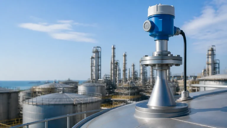
In many industrial settings, mass flow measurement is only one part of a comprehensive fluid management strategy. For instance, in chemical storage or oil blending, flow data from a Rheonik sensor is often cross-referenced with level data from storage tanks to ensure mass balance and inventory accuracy.
Integrating these systems requires high-performance instrumentation across all parameters. For professional-grade industrial level measurement instruments, including radar, ultrasonic, and hydrostatic solutions that complement high-precision flow systems, you can Main Page to review product options and application support. Combining accurate flow data with reliable level monitoring allows for advanced leak detection, overfill prevention, and precise batching control.
Frequently Asked Questions (FAQ)
Can Rheonik sensors measure the flow of non-conductive liquids?
Yes. Unlike electromagnetic flow meters, Coriolis sensors do not require the fluid to be conductive. They work effectively with hydrocarbons, deionized water, and various chemicals.
How often should a Rheonik Coriolis meter be calibrated?
Calibration frequency depends on the criticality of the process and local regulations. In many custody transfer applications, annual calibration is required. For stable process control, a check every 2 to 3 years may be sufficient, provided the zero-point remains stable.
Are these sensors suitable for hygienic applications?
Yes, Rheonik offers specialized RHM models with polished internal surfaces and hygienic connections (such as Tri-Clamp) that meet food and pharmaceutical industry standards.
What is the maximum viscosity these meters can handle?
Coriolis meters are excellent for high-viscosity fluids like resins, polymers, and molasses. The primary limiting factor is the pressure drop across the meter rather than the measurement principle itself.
Conclusion
Rheonik Coriolis mass flow sensors represent a pinnacle of precision engineering for demanding industrial environments. By providing direct mass flow, density, and temperature data in a single device, they offer unparalleled insights into process dynamics. Whether dealing with high-pressure hydrogen or cryogenic chemicals, understanding the Omega tube principle and adhering to strict installation guidelines ensures that these instruments provide reliable service for years. When paired with robust level measurement technologies, they form the backbone of modern, efficient industrial automation systems.