E&h Radar Level Transmitter
E&h Radar Level Transmitter
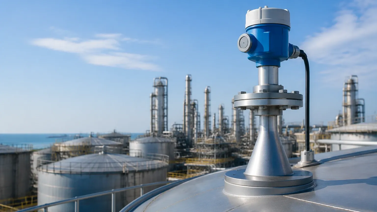
In the realm of industrial process automation, the ability to accurately monitor the contents of a vessel without physical contact is a critical requirement for safety, efficiency, and inventory management. The e&h radar level transmitter, specifically the Micropilot series, has established itself as a benchmark for non-contact microwave level measurement. These instruments are designed to operate in challenging environments where temperature fluctuations, high pressure, and corrosive vapors would render traditional contact-based sensors unreliable.
This guide provides a comprehensive technical overview of radar level measurement principles, the specific capabilities of the e&h radar level transmitter portfolio, and practical engineering considerations for selection and installation in industrial applications.
Principles of Radar Level Measurement
Radar level transmitters operate on the "Time of Flight" (ToF) principle. The device emits a high-frequency electromagnetic wave—typically in the gigahertz (GHz) range—from its antenna toward the surface of the medium. This signal travels at the speed of light. When the wave hits the surface of the product, a portion of the energy is reflected back to the transmitter due to the change in the dielectric constant ($ε_r$) between the air/gas space and the material being measured.
The transmitter receives the reflected echo and calculates the distance ($D$) based on the time delay ($t$) between transmission and reception using the formula:
$$D = \frac{c \times t}{2}$$
Where $c$ is the speed of light. Once the distance to the surface is known, the device subtracts this value from the total tank height (the calibration zero point) to determine the actual level of the product.
Pulse Radar vs. FMCW
There are two primary methods used by an e&h radar level transmitter to process these signals:
1. Pulse Radar: The transmitter emits a series of short microwave pulses and measures the time it takes for each pulse to return. This method is energy-efficient and suitable for a wide range of standard applications.
2. FMCW (Frequency Modulated Continuous Wave): The transmitter emits a continuous signal with a constantly changing frequency. The distance is calculated by measuring the frequency difference between the emitted and received signals. FMCW is often preferred for high-precision requirements and applications with low-reflectivity surfaces (low dielectric constants).
Technical Overview of the Micropilot Series
The e&h radar level transmitter family is categorized primarily by the frequency of the signal and the nature of the medium (liquid vs. solid). Understanding these distinctions is vital for selecting the correct instrument from the Main Page of any industrial supplier.
26 GHz vs. 80 GHz Technology
* 26 GHz Transmitters: These are the traditional workhorses of the industry. They offer a balance between signal strength and the ability to penetrate moderate foam or steam. They are widely used in larger tanks where a slightly wider beam angle is acceptable.
* 80 GHz Transmitters: The shift toward 80 GHz technology represents a significant advancement. The higher frequency allows for a much narrower beam angle (as small as 3 degrees). This precision enables the transmitter to avoid internal obstructions like agitators, heating coils, or baffles, making it ideal for small vessels or complex geometries.
Application-Specific Models
* Micropilot FMR10/FMR20: Compact, cost-effective units designed for the water and wastewater industry. They often feature Bluetooth commissioning for ease of use in remote locations.
* Micropilot FMR5x Series: The standard for process industries (Chemical, Oil & Gas). These units offer high-temperature and high-pressure ratings, with specialized antennas for corrosive environments.
* Micropilot FMR6x Series: Utilizing 80 GHz technology, these are designed for high-accuracy liquid measurement and challenging solids applications where dust and steep angles of repose are present.
Selection Criteria for Radar Transmitters
Choosing the right e&h radar level transmitter requires a detailed analysis of the process conditions. The following table outlines the primary factors that influence model selection:
| Criteria | Impact on Measurement | Recommendation |
| :— | :— | :— |
| Dielectric Constant ($ε_r$) | Determines the strength of the reflected echo. | For $ε_r < 1.9$, use high-sensitivity 80 GHz units or guided wave radar. |
| Process Temperature | Can affect antenna materials and electronics. | Standard units handle up to 150°C (302°F); specialized units reach 450°C (842°F). |
| Process Pressure | Affects the mechanical seal of the antenna. | Vacuum to 160 bar (2320 psi) options are available. |
| Tank Geometry | Internal obstructions can cause false echoes. | Use 80 GHz for narrow tanks or tanks with internal structures. |
| Medium Surface | Turbulence, foam, or dust can scatter signals. | Use drip-off antennas for condensation; use large horn antennas for solids. |
Installation Considerations and Best Practices
Proper installation is the most critical factor in ensuring the long-term reliability of an e&h radar level transmitter. Even the most advanced sensor will fail to provide accurate data if it is mounted incorrectly.
Nozzle Geometry
The mounting nozzle should be as short and wide as possible. If the nozzle is too long or narrow, the radar signal may reflect off the nozzle walls, creating a "ringing" effect that masks the true level signal. Ideally, the antenna should extend at least 10 mm (0.4 inches) below the bottom of the nozzle.
Positioning and Clearance
* Wall Distance: The transmitter should not be mounted too close to the vessel wall. A general rule is to maintain a distance of at least 1/6th of the tank diameter from the wall to prevent interference.
* Inlet Stream: Never install the transmitter directly above the filling stream. The turbulence and the falling material will cause significant signal noise.
* Agitators: If the tank has an agitator, the radar beam should be positioned to avoid the blades. If this is impossible, most modern transmitters include "Mapping" or "False Echo Suppression" software to ignore static or periodic reflections from the blades.
Orientation
For liquid applications, the transmitter must be mounted vertically (perpendicular to the liquid surface). For solids applications, such as silos containing grain or minerals, an alignment device may be necessary to tilt the transmitter toward the angle of repose to maximize the reflected signal.
Limitations and Environmental Challenges
While radar technology is robust, it is not a universal solution. Engineers must be aware of specific limitations:
1. Extreme Foam: While radar can penetrate some foam, thick, dense foam (like shaving cream) can absorb the microwave signal entirely. In such cases, a hydrostatic level transmitter or a guided wave radar may be more appropriate.
2. Low Dielectric Materials: Hydrocarbons like liquid nitrogen or certain oils have very low dielectric constants. If the $ε_r$ is too low, the signal passes through the liquid and reflects off the bottom of the tank instead. This can be mitigated by using a stilling well or a bypass chamber.
3. Heavy Build-up: Although many e&h radar level transmitter models feature "Drip-off" PTFE antennas to shed condensation, heavy crystalline build-up or thick mud on the antenna face will eventually attenuate the signal, requiring periodic cleaning or the use of an air purging system.
Maintenance and Troubleshooting
One of the primary advantages of non-contact radar is the minimal maintenance required. Since there are no moving parts and no contact with the medium, mechanical wear is non-existent. However, periodic verification is recommended.
* Signal Strength (SNR): Monitor the Signal-to-Noise Ratio. A significant drop in SNR often indicates build-up on the antenna or a change in the process medium's properties.
* Echo Map Analysis: Periodically review the envelope curve (the visual representation of the radar echoes). If new peaks appear, they may represent new internal obstructions or scaling on the tank walls.
* Calibration: While the factory calibration is usually sufficient, a "dry run" or manual dip-tape measurement should be performed during commissioning to verify the zero and span points.
Frequently Asked Questions (FAQ)
Q: Can a radar level transmitter measure through a plastic tank lid?
A: Yes. Microwaves can penetrate non-conductive materials like plastic, GRP, or glass. This allows the e&h radar level transmitter to be mounted outside the tank, measuring through a sight glass or a plastic roof, which is ideal for highly corrosive acids.
Q: What is the difference between Radar and Ultrasonic sensors?
A: Ultrasonic sensors use sound waves, which require a medium (air) to travel and are affected by temperature, pressure, and gas composition. Radar uses electromagnetic waves, which work in a vacuum and are largely unaffected by the gas space conditions, making radar more accurate for complex industrial processes.
Q: Is 80 GHz always better than 26 GHz?
A: Not necessarily. While 80 GHz offers better focus and smaller antennas, 26 GHz can be more effective in applications with heavy foam or where the antenna must be mounted in a very long nozzle where 80 GHz might suffer from multiple reflections.
Q: How does the dielectric constant affect the range?
A: The lower the dielectric constant, the less energy is reflected. Consequently, the maximum effective measuring range of the transmitter decreases as the $ε_r$ of the medium decreases.
For engineers and procurement professionals looking to integrate these technologies into their facilities, reviewing a wide range of product options and application support is essential. Detailed specifications and alternative industrial solutions can be found on the Main Page of our technical resource center, where we provide the necessary documentation to ensure your level measurement strategy is both accurate and cost-effective.