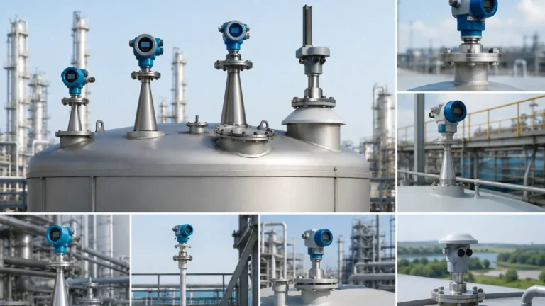
Pilotrek Pulse Radar Level Transmitter
Engineering Guide: Pilotrek Pulse Radar Level Transmitter for Industrial Applications
In the landscape of industrial process control, accurate level measurement is a fundamental requirement for safety, inventory management, and process efficiency. Among the various technologies available, the pilotrek pulse radar level transmitter has emerged as a standard for non-contact measurement in both liquid and solid applications. This guide provides a technical overview of pulse radar technology, selection criteria, and engineering considerations for integrating these instruments into industrial environments.
Understanding the Measurement Principle: Time of Flight (ToF)
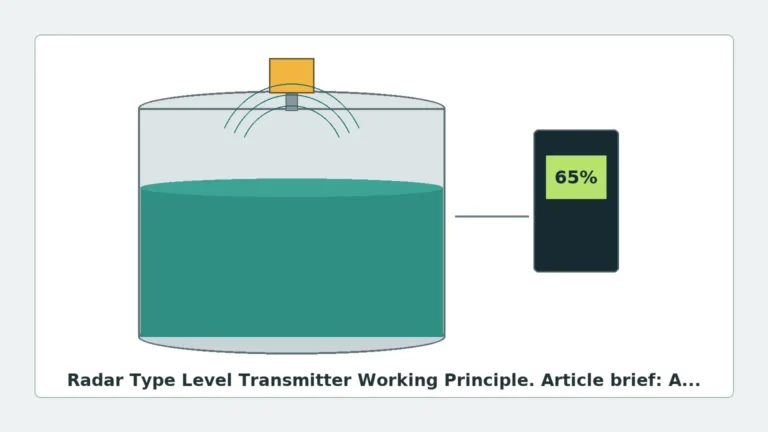
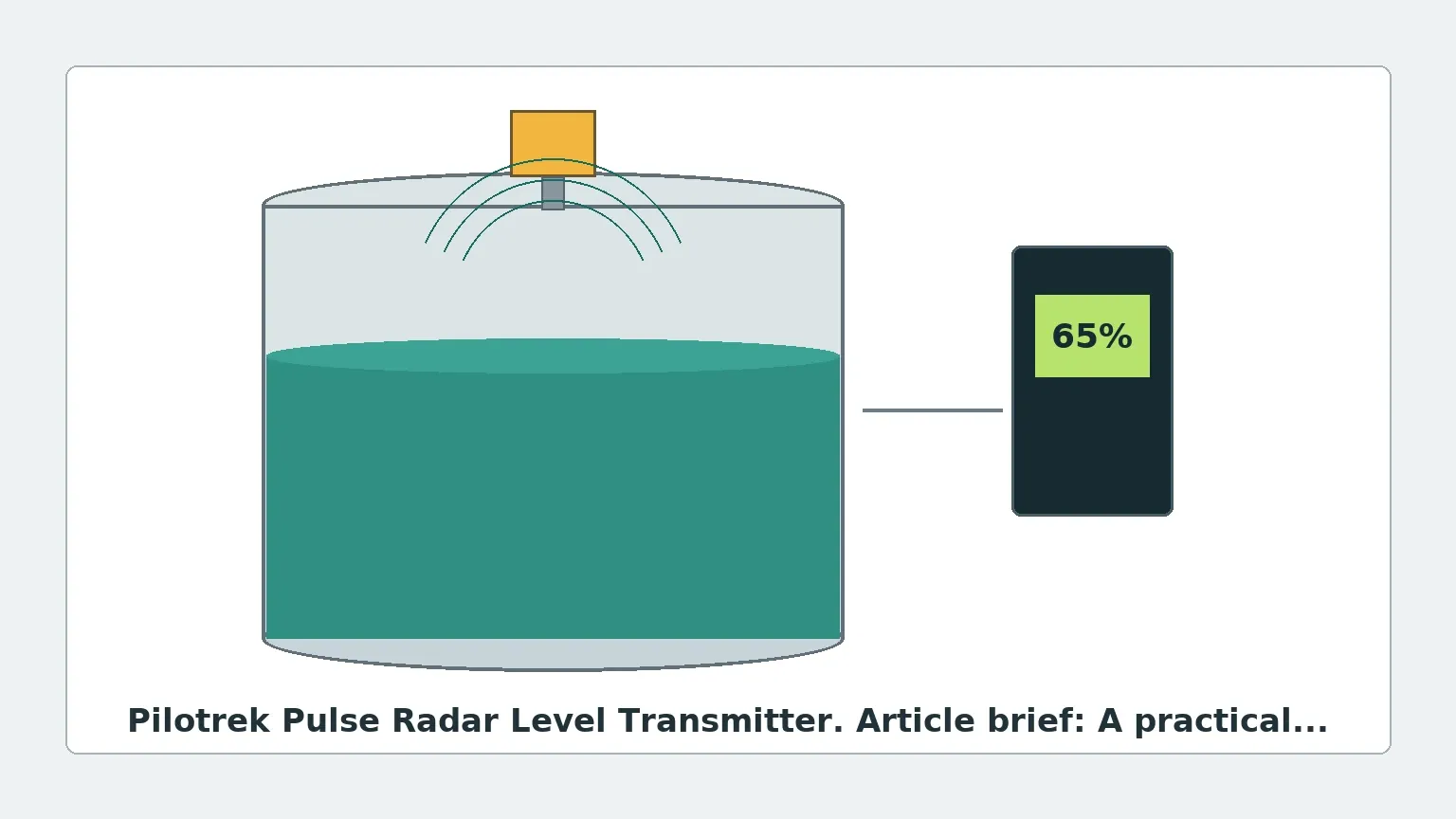
Before selecting a specific instrument, it is essential to understand the underlying physics of radar-based measurement. Radar Level Meters generally operate on the Time of Flight (ToF) principle. This involves the emission of electromagnetic waves toward the surface of the medium being measured.
Pulse Radar vs. FMCW
There are two primary methods of radar measurement: Frequency Modulated Continuous Wave (FMCW) and Pulse Radar. The pilotrek pulse radar level transmitter utilizes the pulse method. In this configuration, the device emits short microwave pulses (typically in the 24 GHz to 80 GHz range) at a specific repetition rate. These pulses travel at the speed of light ($c$).
When the pulse hits the surface of the product, a portion of the energy is reflected back toward the antenna. The instrument’s electronics measure the time interval ($t$) between the emission and the reception of the signal. The distance ($D$) from the reference point to the product surface is calculated using the formula:
$$D = \frac{c \times t}{2}$$
Because the speed of light is constant through the air (or vapor space) regardless of temperature or pressure fluctuations, pulse radar offers high stability compared to ultrasonic methods, which are sensitive to the speed of sound variations in different gas compositions.
Technical Features of the Pilotrek Pulse Radar Level Transmitter
The Pilotrek series is designed to handle challenging industrial conditions where contact-based measurement is either impractical or impossible. Key features typically include:
* Non-Contact Measurement: Since no part of the sensor touches the medium, it is ideal for corrosive, viscous, or abrasive materials.
* High Frequency Operation: Operating at frequencies such as 24 GHz allows for smaller antenna sizes and narrower beam angles, which is critical for avoiding internal tank obstructions.
* Two-Wire Technology: Most modern units utilize a 4-20 mA loop-powered system with HART protocol, simplifying integration into existing DCS or PLC architectures.
* Advanced Signal Processing: Sophisticated algorithms are used to filter out "false echoes" caused by agitators, heating coils, or tank walls.
Practical Selection Criteria
Selecting the correct configuration for a pilotrek pulse radar level transmitter requires a detailed analysis of the process environment. The following table outlines the primary considerations for equipment selection:
Selection Matrix for Radar Level Meters
| Parameter | Requirement/Condition | Recommended Configuration |
| :— | :— | :— |
| Medium Type | Clean liquids, water-based | Standard Horn or Rod antenna |
| Medium Type | Corrosive chemicals (Acids/Bases) | PTFE-coated or Plastic Encapsulated antenna |
| Surface Condition | Turbulent or agitated liquids | High-frequency (80 GHz) or larger horn antenna |
| Process Temperature | Up to 100°C (212°F) | Standard process seal |
| Process Temperature | 100°C to 200°C (392°F) | High-temperature extension / Cooling fin |
| Process Pressure | Vacuum to 3 bar (43 psi) | Standard flange/thread |
| Process Pressure | 3 bar to 40 bar (580 psi) | High-pressure glass-to-metal seal |
| Dielectric Constant (Er) | Low Er (e.g., Hydrocarbons < 2.0) | High-sensitivity electronics or Still-pipe |
The Role of the Dielectric Constant (Er)
The dielectric constant of the medium is the most critical factor in signal reflection. Materials with high dielectric constants (like water, Er ≈ 80) reflect radar signals very well. Hydrocarbons and oils (Er ≈ 1.9 to 2.5) reflect much less energy. When using a pulse radar transmitter on low-dielectric materials, engineers must ensure the device has sufficient sensitivity or utilize a bypass pipe/still-well to concentrate the signal.
Installation and Engineering Considerations
Proper installation is paramount to the reliability of any Radar Level Meters installation. Even the most advanced pilotrek pulse radar level transmitter will fail to provide accurate data if mounted incorrectly.
1. Nozzle Geometry
The mounting nozzle should be as short and wide as possible. If the nozzle is too long or narrow, the radar pulse may reflect off the internal edges of the nozzle before it even enters the tank, creating a "dead zone" or signal interference at the top of the measurement range.
2. Beam Angle and Obstructions
Every radar antenna has a specific beam angle (e.g., 8°, 10°, or 20°). The "footprint" of the radar signal expands as the distance increases. Engineers must ensure that no internal tank structures—such as ladders, support beams, or inlet pipes—intersect the radar beam. If an obstruction is unavoidable, the transmitter's "false echo suppression" or "background masking" software must be used during commissioning to map out these static reflections.
3. Mounting Position
* Avoid the Center: Do not mount the transmitter in the exact center of a domed tank roof, as this can lead to multiple reflections that confuse the sensor.
* Wall Distance: Maintain a minimum distance from the tank wall (typically 1/6th of the tank diameter) to prevent interference from wall weld seams or buildup.
* Inlet Stream: Never mount the sensor directly over the filling stream, as the falling material will reflect the signal and cause erratic readings.
Application Risks and Limitations
While pulse radar is highly versatile, it is not a universal solution for every process. Engineers should be aware of the following risks:
* Heavy Foam: Dense, thick foam can absorb the radar signal entirely, preventing any reflection from reaching the antenna. In such cases, a guided wave radar or a mechanical float-based system may be more appropriate.
* Heavy Dust/Condensation: While radar can penetrate some dust, extreme buildup on the antenna face can attenuate the signal. For these environments, an antenna with a purging connection (using compressed air) is recommended to keep the lens clean.
* Vacuum Conditions: While radar works in a vacuum, the sealing of the process connection becomes a critical failure point. Specialized glass-to-metal seals are required to maintain tank integrity.
Maintenance and Troubleshooting
One of the primary advantages of the pilotrek pulse radar level transmitter is its low maintenance requirement due to the lack of moving parts. However, periodic checks are advised:
1. Antenna Inspection: Check for material buildup or crystallization on the antenna. PTFE-faced antennas are generally self-cleaning in condensing environments, but sticky media may require manual cleaning.
2. Signal Strength Monitoring: Modern transmitters provide a signal-to-noise ratio or echo amplitude value. A significant drop in this value over time may indicate antenna fouling or a change in the medium's properties.
3. Loop Verification: Ensure the 4-20 mA output matches the digital value shown on the transmitter display to rule out wiring or scaling issues in the control system.
Frequently Asked Questions (FAQs)
Q: Can a pulse radar transmitter measure the interface between two liquids?
A: Generally, no. Standard pulse radar reflects off the first surface it encounters. For liquid-liquid interface measurement (e.g., oil over water), Guided Wave Radar (GWR) is typically required, as it allows part of the signal to pass through the top layer.
Q: How does the pilotrek pulse radar level transmitter handle internal agitators?
A: The device uses "Agitator Mapping" or "False Echo Suppression." The user runs a scan while the agitator is moving (or at a known position), and the software identifies those specific reflections as noise to be ignored.
Q: Is there a minimum distance the sensor can measure?
A: Yes, this is known as the "Blocking Distance" or "Dead Zone." It is typically the area immediately below the antenna (0.1m to 0.5m depending on the model). Level changes within this zone cannot be measured accurately.
Q: Does the gas composition in the tank affect the measurement?
A: Unlike ultrasonic sensors, radar is largely unaffected by gas composition, pressure, or temperature, because electromagnetic waves do not require a medium for travel. However, very high-pressure gases (like high-pressure CO2) can slightly change the dielectric constant of the vapor space, requiring a small correction factor in high-precision applications.
Conclusion
The pilotrek pulse radar level transmitter represents a robust solution for modern industrial level measurement. By understanding the dielectric properties of the medium and adhering to strict installation guidelines regarding beam angles and nozzle geometry, engineers can achieve highly accurate and maintenance-free level monitoring. For complex applications involving extreme temperatures or low-dielectric fluids, consulting technical specifications for specialized Radar Level Meters is recommended to ensure long-term operational reliability.