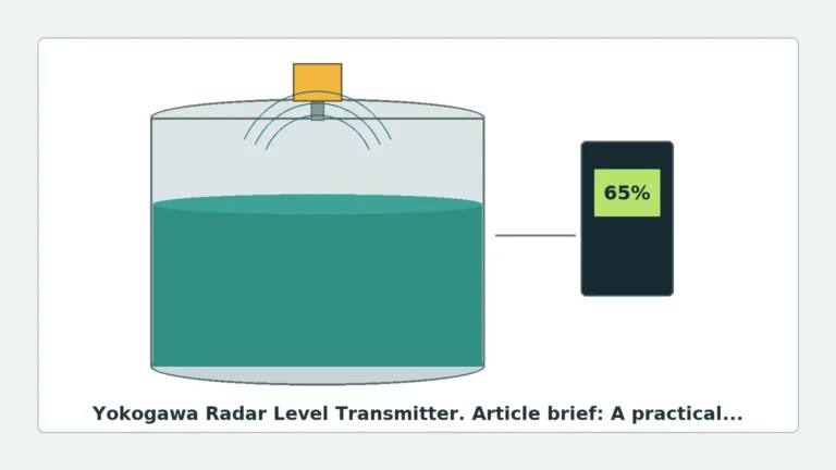
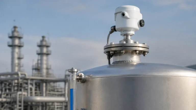
Different Types of Radar Level Transmitter
Different Types of Radar Level Transmitter: A Technical Engineering Guide
In the landscape of industrial process automation, selecting the correct level measurement technology is critical for operational safety, inventory accuracy, and process efficiency. Radar level transmitters have emerged as a leading solution due to their non-contact nature and ability to operate under extreme temperatures and pressures. However, "radar" is not a monolithic technology. Understanding the different types of radar level transmitter is essential for engineers and procurement specialists to ensure the selected instrument matches the specific constraints of their application.
Measurement Principles: Pulse vs. FMCW
Before categorizing radar transmitters by their physical form or frequency, it is important to understand the two primary electronic principles used to determine distance: Pulse Radar and Frequency Modulated Continuous Wave (FMCW).
Pulse Radar (Time of Flight)
Pulse radar transmitters emit a microwave signal in short, discrete bursts. These pulses travel at the speed of light, reflect off the surface of the medium, and return to the sensor. The instrument measures the "Time of Flight" (ToF)—the interval between the emission and the reception of the pulse. Because the speed of light is constant, the distance is calculated as:
*Distance = (Speed of Light × Time of Flight) / 2*
Pulse radar is generally more power-efficient and is often used in battery-powered or two-wire loop-powered applications. However, it may struggle with very low dielectric constant (εr) materials where the reflected signal is weak.
Frequency Modulated Continuous Wave (FMCW)
FMCW radar does not send pulses. Instead, it transmits a continuous signal with a frequency that changes linearly over time (a frequency sweep). When the reflected signal is received, it is compared to the signal currently being transmitted. The difference in frequency (the "beat frequency") is directly proportional to the distance the signal has traveled.
FMCW technology typically offers higher accuracy and a better signal-to-noise ratio than pulse radar. This makes it the preferred choice for high-precision custody transfer or applications involving heavy vapor, dust, or turbulent surfaces. Many modern Radar Level Meters utilize FMCW at high frequencies to provide millimeter-level precision.
Contact vs. Non-Contact Radar
Radar transmitters are broadly divided into two physical configurations: Guided Wave Radar (GWR) and Non-Contact Radar.
Guided Wave Radar (GWR)
Guided Wave Radar is a contact-based technology. It utilizes a physical probe (a cable, rod, or coaxial tube) to guide the microwave pulse from the sensor head down to the liquid or solid surface.
* Advantages: Since the energy is concentrated along the probe, GWR is highly effective for measuring media with low dielectric constants (as low as εr 1.4). It is also unaffected by foam, dust, or heavy turbulence that might scatter a non-contact signal.
* Limitations: Because it is a contact technology, the probe is subject to corrosion, mechanical stress, and material buildup. It is not suitable for applications where the probe might interfere with agitators or where hygienic requirements forbid internal probes.
Non-Contact Radar
Non-contact radar transmitters emit microwaves through the air. They are mounted at the top of the vessel and do not touch the process media.
* Advantages: Zero maintenance regarding probe wear, ideal for corrosive or sterile environments, and easy to install without emptying the tank.
* Limitations: The signal can be affected by internal tank obstructions (ladders, pipes), heavy foam, or extremely dusty environments where the signal might be attenuated.
Frequency Bands and Their Applications
The frequency at which a radar transmitter operates significantly influences its beam angle, sensitivity, and ability to handle process interference. There are three primary frequency categories used in industrial instrumentation.
1. Low Frequency (6 GHz to 10 GHz)
Often referred to as C-band radar, these transmitters have longer wavelengths. They are less affected by steam, vapor, and foam. However, they require larger antennas (horn diameters up to 250 mm) to achieve a manageable beam angle. They are typically used in heavy industrial applications like asphalt tanks or large outdoor water reservoirs.
2. High Frequency (24 GHz to 26 GHz)
K-band radar is the traditional "workhorse" of the industry. It offers a balance between antenna size and accuracy. With a smaller beam angle than 6 GHz models, it can be used in smaller tanks with fewer internal obstructions. It is widely used for chemical storage and oil-water separation tanks.
3. Ultra-High Frequency (80 GHz)
W-band radar represents the latest advancement in level measurement. Operating at 80 GHz allows for a very narrow beam angle (as small as 3°).
* Precision: High frequency allows for a wider bandwidth, resulting in much higher resolution.
* Small Footprint: High-frequency waves can be focused using small antennas, allowing installation through small 1-inch (25 mm) nozzles.
* Obstacle Avoidance: The narrow beam can easily bypass internal heating coils, agitators, or ladders that would cause false echoes in lower-frequency models.
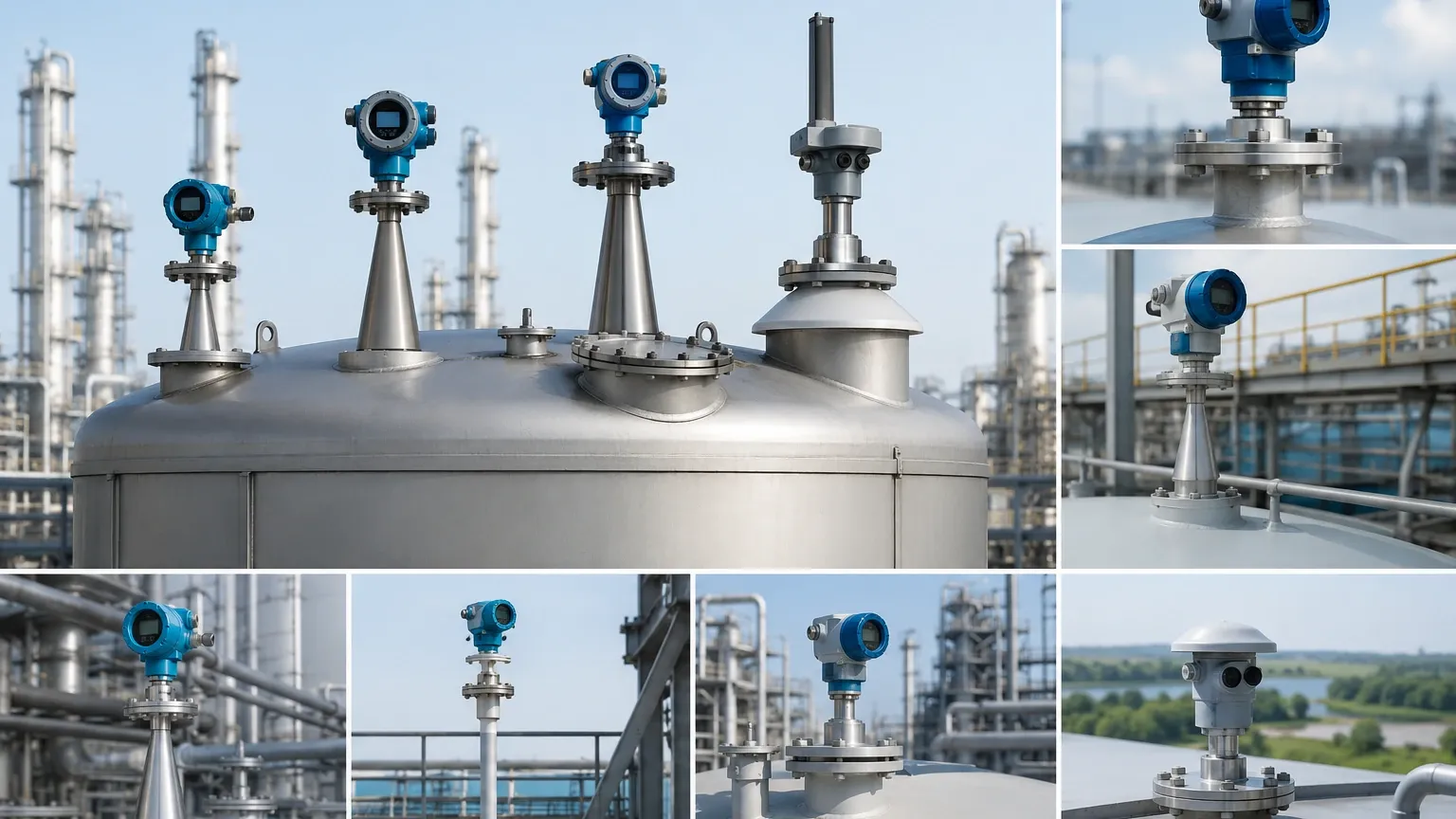
Antenna Types and Selection
The antenna is the interface between the transmitter electronics and the process. Selecting the right antenna type is as important as selecting the frequency.
| Antenna Type | Best Use Case | Key Characteristics |
| :— | :— | :— |
| Horn Antenna | Standard liquid storage | Durable, versatile, available in various sizes (2" to 10"). |
| Parabolic Antenna | Long-range solids | Large surface area to capture reflections from uneven solid surfaces. |
| Rod/PTFE Shielded | Corrosive chemicals | Encapsulated in plastic to prevent acid/alkali damage. |
| Lens Antenna | 80 GHz applications | Flat surface, resistant to condensation and buildup, fits small nozzles. |
| Drop Antenna | Dusty environments | Specifically shaped to prevent dust accumulation on the emitting surface. |
Selection Criteria for Different Types of Radar Level Transmitter
When evaluating different types of radar level transmitter, engineers should use a systematic approach based on the following process parameters:
1. Dielectric Constant (εr): This is the most critical factor. Materials with high εr (like water, εr ≈ 80) reflect signals strongly. Materials with low εr (like hydrocarbons or plastic pellets) reflect weakly. For εr < 2.0, Guided Wave Radar or high-frequency FMCW is usually required.
2. Process Temperature and Pressure: Standard radar units handle up to 150°C (302°F), but specialized high-temperature versions can reach 450°C (842°F) using ceramic seals and cooling fins.
3. Tank Geometry: Small, tall tanks or tanks with many internal structures favor 80 GHz radar due to its narrow beam. Large, open basins may be better served by lower-cost 26 GHz or ultrasonic sensors if conditions allow.
4. Media State: Is it a liquid, a slurry, or a solid? Solids require specialized algorithms to handle the "angle of repose" (the slope of the material pile).
Installation Considerations and Best Practices
Even the most advanced radar transmitter will fail if installed incorrectly. Follow these engineering guidelines for optimal performance:
* Nozzle Height and Diameter: The antenna should ideally extend slightly beyond the bottom of the mounting nozzle to prevent "ringing" or signal interference from the nozzle walls.
* Distance from Wall: Never mount a radar transmitter in the center of a tank (which can cause multiple reflections) or too close to the wall (which causes signal attenuation). A common rule of thumb is to mount the sensor at 1/6th to 1/4th of the tank diameter from the wall.
* Avoiding Obstructions: Ensure the signal path is clear of agitator blades, ladders, and inflow pipes. If an obstruction is unavoidable, use the "False Echo Suppression" or "Background Subtraction" feature in the transmitter software to map out the static interference.
* Alignment: For solids measurement, the radar may need to be mounted on an aiming flange (swivel mount) to align the beam perpendicular to the material slope for maximum signal return.
Limitations and Application Risks
While radar is highly versatile, it is not a "one-size-fits-all" solution. Engineers must be aware of the following risks:
* Heavy Foam: While some radar types can penetrate light foam, dense "shaving cream" style foam can absorb the microwave signal entirely, leading to a loss of echo. In these cases, Guided Wave Radar is the only reliable radar option.
* Vacuum Conditions: Microwaves do not require a medium to travel, so radar works perfectly in a vacuum. However, the mechanical seals of the transmitter must be rated for vacuum service to prevent air ingress or sensor damage.
* Condensation and Buildup: Heavy condensation on the antenna can refract the signal. Choosing a lens antenna with a PTFE (Teflon) face or using a purging connection (compressed air) can mitigate this.
Frequently Asked Questions (FAQ)
Q: Can radar measure the interface between two liquids?
A: Yes, Guided Wave Radar is excellent for interface measurement (e.g., oil over water). The signal reflects off the top layer and a portion continues through to reflect off the interface of the second liquid, provided the top layer has a lower dielectric constant.
Q: What is the maximum range of a radar level transmitter?
A: Non-contact radar can measure up to 30 meters (approx. 100 feet) for liquids and up to 120 meters (approx. 393 feet) for solids, depending on the frequency and antenna size.
Q: Does dust affect radar measurement?
A: High-frequency radar (80 GHz) and low-frequency radar (6 GHz) handle dust differently. 80 GHz is generally preferred for solids because its narrow beam avoids wall reflections, though extremely thick dust clouds may require a dust-purging system.
Q: Is radar better than ultrasonic level measurement?
A: Radar is generally superior in processes involving high temperature, pressure, vacuum, or vapor. Ultrasonic sensors rely on sound waves, which are affected by air temperature and cannot travel in a vacuum. However, ultrasonic sensors are often more cost-effective for simple water tank applications.
Conclusion
Selecting among the different types of radar level transmitter requires a thorough understanding of the process environment and the physics of microwave propagation. Whether opting for the precision of an 80 GHz FMCW unit or the reliability of a Guided Wave Radar in turbulent conditions, matching the instrument to the application is the key to long-term measurement stability. For technical specifications and model comparisons, engineers should consult with a professional manufacturer to review specific process compatibility.
Download Different Types of Radar Level Transmitter as a PDF