Dp Transmitter for Flow Measurement
Dp Transmitter for Flow Measurement
Differential pressure (DP) flow measurement remains one of the most widely utilized technologies in industrial process control. Despite the emergence of ultrasonic and Coriolis meters, the use of a dp transmitter for flow measurement continues to be the standard in many chemical, water treatment, and oil and gas applications due to its reliability, versatility, and well-understood physical principles. This guide provides a comprehensive technical overview of how these systems function, how to select the appropriate components, and the critical installation factors that ensure long-term accuracy.
Measurement Principles of DP Flow Systems
The fundamental principle underlying the use of a dp transmitter for flow measurement is Bernoulli’s Equation, which describes the relationship between the velocity of a fluid and its pressure. When a fluid moving through a closed pipe encounters a physical restriction, its velocity increases and its static pressure decreases. By measuring the difference between the high pressure (upstream of the restriction) and the low pressure (at or downstream of the restriction), the flow rate can be calculated.
The Square Root Relationship
In most DP flow applications, the relationship between the differential pressure ($ΔP$) and the flow rate ($Q$) is non-linear. Specifically, the flow rate is proportional to the square root of the differential pressure:
$$Q = k \cdot \sqrt{ΔP}$$
Where $k$ is a constant determined by the pipe diameter, the type of restriction (primary element), and the physical properties of the fluid (such as density and viscosity). Because of this square root relationship, a dp transmitter for flow measurement typically requires a "square root extraction" function. This can be performed either within the transmitter's internal electronics or by the control system (PLC/DCS) to provide a linear 4-20mA signal representing the actual flow rate.
The Role of the Primary Element
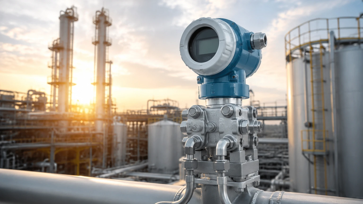
The "primary element" is the hardware installed in the pipe to create the pressure drop. Common examples include orifice plates, Venturi tubes, and flow nozzles. The "secondary element" is the DP transmitter itself, which senses the pressure difference and converts it into an electrical signal.
Types of Primary Elements
Selecting the correct primary element is critical for the performance of the dp transmitter for flow measurement. Each type has distinct advantages regarding accuracy, pressure loss, and cost.
1. Orifice Plates
The orifice plate is a thin metal disk with a precision-machined hole (bore) in the center. It is the most common primary element due to its low cost and ease of installation between standard pipe flanges.
* Advantages: Low initial cost, available in many materials, and standardized by international codes (ISO 5167).
* Limitations: High permanent pressure loss and susceptible to wear or clogging if the fluid contains solids.
2. Venturi Tubes
A Venturi tube consists of a converging conical section, a cylindrical throat, and a diverging recovery section. It is designed to minimize turbulence.
* Advantages: Very low permanent pressure loss (high energy efficiency) and excellent for high-velocity or dirty fluids.
* Limitations: High initial cost, large physical footprint, and difficult to modify once installed.
3. Flow Nozzles
Flow nozzles are essentially a hybrid between an orifice plate and a Venturi tube. They feature a curved inlet leading to a short cylindrical throat.
* Advantages: Better pressure recovery than orifice plates and highly resistant to erosion in high-temperature steam applications.
* Limitations: Higher cost than orifice plates.
4. Pitot Tubes and Annubars
These elements measure the difference between static pressure and impact (dynamic) pressure at a specific point or across the pipe diameter.
* Advantages: Minimal pressure loss and can be installed through a small tap in the pipe.
* Limitations: Lower accuracy at low flow rates and sensitive to flow profile distortions.
Technical Selection Criteria
When specifying a dp transmitter for flow measurement, engineers must evaluate several technical parameters to ensure the device matches the process requirements. For a broader look at industrial instrumentation, users can Review product options and application support to see how these devices integrate into wider automation systems.
| Feature | Orifice Plate | Venturi Tube | Pitot/Annubar |
| :— | :— | :— | :— |
| Accuracy | 0.75% to 2.0% | 0.5% to 1.5% | 1.0% to 3.0% |
| Pressure Loss | High (40-90% of $ΔP$) | Low (10-20% of $ΔP$) | Very Low (<5% of $ΔP$) |
| Relative Cost | Low | High | Medium |
| Typical Fluids | Clean liquids/gases | Slurries, dirty fluids | Large gas ducts |
| Installation | Between flanges | Inline (welded/flanged) | Single probe insertion |
Turndown Ratio
The turndown ratio refers to the range over which the meter can measure accurately. Because of the square root relationship, a standard dp transmitter for flow measurement usually has a turndown of 3:1 or 4:1. To achieve higher turndown (e.g., 10:1), high-performance "smart" transmitters with advanced digital processing are required.
Installation Considerations
The accuracy of a dp transmitter for flow measurement is heavily dependent on how it is installed. Even the most precise transmitter will provide incorrect data if the primary element or the impulse lines are misconfigured.
Straight Pipe Runs
To ensure a stable and predictable flow profile, the primary element must be preceded and followed by straight sections of pipe. These "straight runs" eliminate turbulence caused by elbows, valves, or pumps.
* Upstream: Typically 10 to 40 pipe diameters depending on the upstream disturbance.
* Downstream: Typically 5 pipe diameters.
Impulse Piping
Impulse lines (or sensing lines) carry the pressure from the pipe taps to the transmitter.
1. Slope: Impulse lines should be sloped at least 1:12 (80 mm per meter) to allow trapped air to rise back into the pipe (in liquid service) or condensate to drain (in gas service).
2. Length: Keep impulse lines as short as possible to minimize response lag and reduce the risk of freezing or clogging.
3. Manifolds: A 3-valve or 5-valve manifold should always be used. This allows the transmitter to be isolated, zeroed, and removed without shutting down the process line.
Mounting Orientation
* Liquid Service: The transmitter should be mounted *below* the flow line so that air bubbles rise up and away from the sensor.
* Gas Service: The transmitter should be mounted *above* the flow line so that any moisture or condensate drains back into the process pipe.
* Steam Service: The transmitter is usually mounted below the line, but with "condensate pots" to ensure the sensing diaphragms are protected by a layer of cool water rather than live steam.
Limitations and Challenges
While robust, the use of a dp transmitter for flow measurement has specific limitations that must be managed:
1. Permanent Pressure Loss: The restriction created by the primary element consumes energy. In large-scale pumping systems, this can lead to significant electricity costs over time.
2. Square Root Error: At the bottom 10% of the flow range, the differential pressure is extremely small (1% of the maximum $ΔP$). Small errors in pressure sensing at this level result in large errors in calculated flow.
3. Density Sensitivity: DP flow measurement is an indirect mass flow measurement. If the fluid density changes due to temperature or pressure fluctuations, the flow calculation will be inaccurate unless "compensation" (using additional temperature and pressure sensors) is applied.
4. Impulse Line Clogging: In dirty or viscous fluids, impulse lines can plug, leading to a frozen or drifting signal. Diaphragm seals or purging systems may be required in these instances.
Frequently Asked Questions (FAQ)
Q: Can a DP transmitter measure flow in both directions?
A: Standard orifice-based systems are unidirectional. However, using a bi-directional primary element and a transmitter configured for bi-directional sensing (where 12mA is zero flow) allows for flow measurement in both directions.
Q: Why is my flow reading higher than expected?
A: Common causes include a worn orifice plate (rounded edges), debris buildup in front of the plate, or air trapped in the impulse lines of a liquid system.
Q: What is the difference between a 3-valve and a 5-valve manifold?
A: A 3-valve manifold has two isolation valves and one equalizer valve. A 5-valve manifold adds two vent/drain valves, which are essential for safely bleeding pressure or checking for leaks without disconnecting the transmitter.
Q: How often should a dp transmitter for flow measurement be calibrated?
A: Most modern smart transmitters have excellent long-term stability. While an annual check is standard for critical loops, many facilities extend this to 2-3 years based on historical performance and the criticality of the process.
Summary for Project Planning
Before finalizing the specification of a dp transmitter for flow measurement, project teams should confirm the following:
* Fluid Properties: Confirm viscosity, density, and whether the fluid is corrosive or contains solids.
* Operating Range: Ensure the expected flow range fits within a 4:1 turndown, or opt for a multi-variable transmitter if higher rangeability is needed.
* Pipe Geometry: Verify that there is enough physical space for the required straight pipe runs.
* Maintenance Access: Ensure the transmitter and manifold are accessible for routine zero-checks and calibration.
For engineers and procurement professionals looking for reliable measurement solutions, visiting the Welk Main Page offers a gateway to advanced instrumentation designed for the rigors of modern industrial automation. By understanding the physics of differential pressure and adhering to strict installation standards, facilities can achieve highly accurate and cost-effective flow control.