Continuous Float Level Transmitters
Continuous Float Level Transmitters
In the landscape of industrial automation, accurately monitoring liquid inventory and process cycles is fundamental to operational efficiency and safety. Continuous float level transmitters represent a time-tested, highly reliable technology for providing real-time level data. Unlike point-level switches that only signal when a liquid reaches a specific threshold, continuous transmitters provide an uninterrupted signal across the entire measurement range. This guide explores the mechanical principles, selection criteria, and practical application of these instruments within various industrial sectors.
Understanding the Measurement Principles
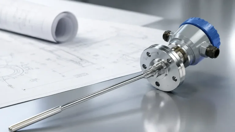
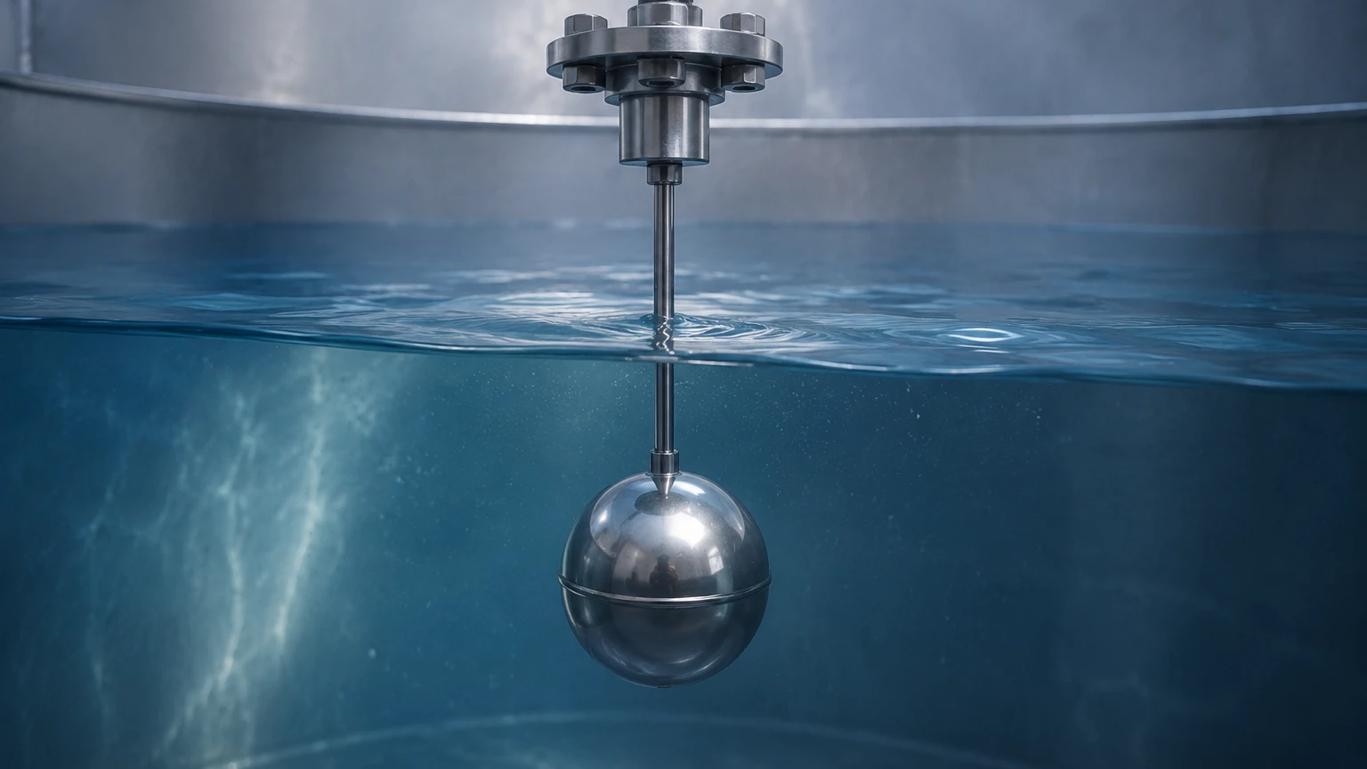
Continuous float level transmitters operate on the principle of buoyancy, utilizing a float that contains an internal magnetic element. As the liquid level rises or falls, the float moves along a stationary sensing stem. There are two primary technologies used within the stem to convert this mechanical movement into an electrical signal: Reed Switch Resistance Chains and Magnetostrictive technology.
Reed Switch Resistance Chain
This is the most common and cost-effective method for continuous float measurement. Inside the sensing stem, a series of reed switches and resistors are arranged in a ladder formation. As the magnetic float moves, it closes the reed switches in its immediate proximity. This action changes the total resistance of the circuit, effectively acting like a sliding potentiometer. An integrated electronic module converts this resistance value into a standard industrial output, such as a 4-20mA analog signal or a digital communication protocol like HART.
The resolution of this type of transmitter is determined by the spacing of the reed switches. Typical resolutions range from 5mm (0.2 in) to 20mm (0.8 in). While not as precise as radar, it is more than sufficient for most bulk storage and process tank applications.
Magnetostrictive Principle
For applications requiring high precision, magnetostrictive continuous float level transmitters are utilized. This technology relies on the "Wiedemann effect." A low-current pulse is sent down a magnetostrictive wire (waveguide) inside the stem. When this pulse reaches the magnetic field of the float, a torsional strain wave is generated and travels back up the wire to a sensor in the transmitter head. By measuring the time of flight between the initial pulse and the return wave, the device calculates the float's position with extreme accuracy, often within ±1mm (0.04 in).
Key Components and Material Selection
To ensure longevity in harsh industrial environments, selecting the correct materials for continuous float level transmitters is critical. As a professional manufacturer, Welk provides these instruments in various configurations to suit diverse chemical and physical requirements.
1. The Sensing Stem: This is the vertical tube that houses the electronics. It must be rigid and resistant to the process media. Common materials include 316L Stainless Steel for general use and water treatment, or plastics like PVC, Polypropylene (PP), and PVDF for highly corrosive acids and bases.
2. The Float: The float is the only moving part and must be engineered to withstand the process pressure and temperature while remaining buoyant. Stainless steel floats are standard for high-pressure applications, while plastic floats are used for chemical compatibility. The specific gravity (SG) of the float must be lower than the minimum SG of the liquid being measured.
3. The Housing: The transmitter head or housing contains the signal conditioning electronics. In many oil and gas or chemical applications, these housings must be explosion-proof or intrinsically safe to meet ATEX or IECEx standards.
Selection Criteria for Industrial Applications
When specifying continuous float level transmitters, engineers must evaluate several variables to ensure the instrument performs reliably over its service life.
Specific Gravity (SG) Compatibility
Buoyancy is the core of the measurement. If a liquid has a low specific gravity (e.g., light hydrocarbons with an SG of 0.65), a standard float designed for water (SG 1.0) may sink. Manufacturers provide floats weighted specifically for different density ranges. It is standard practice to select a float with an SG at least 0.1 lower than the liquid to ensure a consistent floating position.
Temperature and Pressure Limits
Mechanical floats are subject to physical deformation if pressure limits are exceeded. High-pressure tanks (e.g., boiler feed water or liquefied gases) require reinforced stainless steel floats. Similarly, the internal electronics and reed switches have thermal limits. Standard models typically handle up to 100°C (212°F), while specialized high-temperature versions can reach 200°C (392°F) or higher.
Viscosity and Coating Tendencies
Continuous float level transmitters are best suited for clean, non-viscous liquids. If a liquid is highly viscous or prone to crystallization (like heavy crude oil or concentrated sugar syrups), the float may stick to the stem, leading to false readings. In such cases, non-contact methods like ultrasonic or radar may be preferred, though specialized "large-clearance" floats can sometimes mitigate these issues.
Practical Selection Table
The following table provides a general comparison of the two main types of continuous float level transmitters to assist in the initial engineering phase.
| Feature | Reed Switch Type | Magnetostrictive Type |
| :— | :— | :— |
| Accuracy | 5mm to 20mm | ±1mm or better |
| Standard Range | Up to 6 meters (19.7 ft) | Up to 4 meters (13.1 ft) |
| Cost | Economical | Higher |
| Output Options | 4-20mA, 0-10V | 4-20mA, HART, Modbus |
| Durability | High (No moving electronic parts) | High (Requires stable power) |
| Best Use Case | Water tanks, diesel storage | Chemical dosing, custody transfer |
For more specific technical data and to evaluate different model configurations for your facility, you can visit the Main Page for a comprehensive overview of available measurement solutions.
Installation and Maintenance Guidelines
Correct installation is paramount for the accuracy of continuous float level transmitters. Because these devices rely on a vertical stem, any deviation from the vertical axis can increase friction between the float and the stem, potentially causing the float to hang up.
Positioning and Clearance
* Vertical Alignment: The transmitter should be installed as close to 90 degrees vertical as possible. A tilt of more than 5 degrees can significantly impact performance.
* Obstructions: Ensure the float has a clear path of travel. Internal tank structures like baffles, ladders, or agitators must be avoided. A minimum clearance of 50mm (2 in) around the float is generally recommended.
* Turbulence: In tanks with high turbulence or near-inlet pipes, the float may bounce erratically. In these scenarios, the use of a stilling well (a perforated pipe that surrounds the stem) is necessary to provide a calm surface for the float.
Electrical Considerations
To prevent signal interference, shielded cables should be used for the 4-20mA output, especially in environments with large motors or variable frequency drives (VFDs). The shield should be grounded at the controller end only to avoid ground loops.
Maintenance
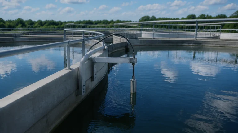
While continuous float level transmitters are relatively low-maintenance, periodic inspection is advised. In water treatment applications, calcium buildup or biological growth can accumulate on the stem. A simple wipe-down during scheduled shutdowns is usually sufficient to maintain smooth float movement.
Limitations and Common Risks
While highly reliable, continuous float level transmitters are not universal solutions. Understanding their limitations prevents application failure.
* Mechanical Wear: Because there is physical contact between the float's inner bushing and the stem, extremely high-cycle applications (constant rapid fluctuations) can eventually lead to wear.
* Magnetic Interference: Since the sensing principle is magnetic, the presence of strong external magnetic fields or large amounts of ferrous particulate (iron filings) in the liquid can interfere with the sensor or cause debris to stick to the float.
* Dead Zones: Every transmitter has a "dead zone" at the very top and bottom of the stem where the float cannot travel or where the sensors cannot detect it. Engineers must account for these zones (typically 50-100mm) when calculating the total usable volume of a tank.
Frequently Asked Questions (FAQ)
Q: Can continuous float level transmitters be used in pressurized tanks?
A: Yes, provided the float is rated for the specific pressure. Stainless steel floats can typically handle pressures up to 30 Bar (435 PSI), though custom high-pressure versions are available for more demanding requirements.
Q: What happens if the liquid density changes?
A: Since the float sits at a specific level based on buoyancy, a significant change in liquid density will cause the float to sit slightly higher or lower in the liquid. For most industrial water and fuel applications, these density changes are negligible, but for precise chemical blending, this must be factored into the calibration.
Q: Are these sensors suitable for food and beverage applications?
A: Yes, provided they are manufactured with sanitary finishes (e.g., Ra < 0.8μm) and use food-grade materials like 316L stainless steel or specialized plastics. Welk offers various configurations that meet industrial hygiene standards.
Q: How do I calibrate a continuous float level transmitter?
A: Most modern transmitters come pre-calibrated from the factory based on the ordered length. However, zero and span adjustments can usually be made via a local display, a HART communicator, or internal potentiometers to align the 4mA and 20mA points with the physical tank levels.
Conclusion
Continuous float level transmitters remain a cornerstone of industrial level measurement due to their simplicity, reliability, and ease of integration. By understanding the nuances of reed switch versus magnetostrictive technologies and carefully considering material compatibility and specific gravity, engineers can implement a solution that provides years of accurate service. Whether managing water treatment facilities, chemical storage, or industrial automation processes, these instruments offer a balance of performance and cost-effectiveness that is difficult to match with more complex non-contact technologies. For further technical assistance and product selection, reviewing the available options on the Main Page is a recommended next step for project planning.