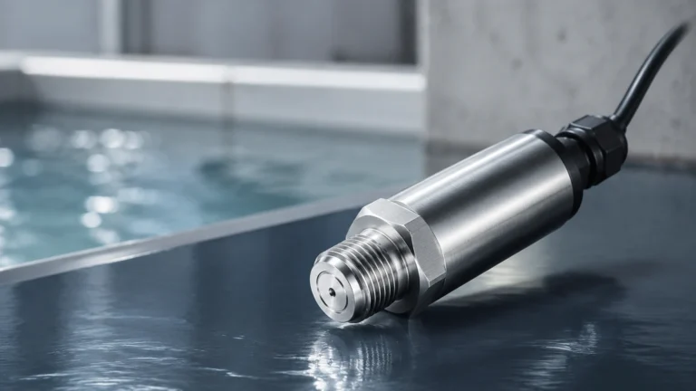
Hydrostatic Tank Sensors
Hydrostatic Tank Sensors
Hydrostatic tank sensors represent one of the most reliable and widely adopted technologies for liquid level measurement in industrial environments. By leveraging the fundamental laws of physics—specifically the relationship between pressure and fluid depth—these instruments provide a continuous and accurate reading of tank levels. Whether used in water treatment, chemical processing, or oil and gas storage, understanding the nuances of hydrostatic technology is essential for ensuring process efficiency and safety.
In this guide, we examine the underlying principles of hydrostatic measurement, the various sensor configurations available, and the critical factors engineers must consider when selecting and installing these devices for industrial applications.
Measurement Principles of Hydrostatic Level Sensing
The operation of hydrostatic tank sensors is based on the principle that the pressure at a specific point within a static liquid is proportional to the height of the liquid column above that point. This is described by the hydrostatic pressure formula:
P = ρ · g · h
Where:
* P is the hydrostatic pressure (measured in Pascals or bar).
* ρ (rho) is the density of the liquid (kg/m³).
* g is the gravitational acceleration (approximately 9.81 m/s²).
* h is the height of the liquid column (meters).
In a practical industrial setting, if the density of the liquid remains constant, the pressure measured at the bottom of the tank is a direct indicator of the liquid level. For example, a water column (density ≈ 1000 kg/m³) with a height of 10 meters (32.8 ft) exerts a pressure of approximately 1 bar (14.5 psi) at the base.
Atmospheric Pressure Compensation
For sensors installed in open or vented tanks, the instrument must account for changes in atmospheric pressure. If the sensor only measured absolute pressure, a drop in barometric pressure would be interpreted as a drop in liquid level. To prevent this error, hydrostatic tank sensors typically use a "gauge pressure" reference. This is achieved via a small vent tube integrated into the sensor cable or housing, which allows the back of the pressure-sensing diaphragm to be exposed to the current atmospheric pressure, effectively canceling it out of the measurement.
Types of Hydrostatic Tank Sensors
Depending on the tank geometry and the nature of the liquid, different sensor designs are employed. As a professional manufacturer, Welk provides several variations to meet diverse industrial needs.
1. Submersible Level Transmitters
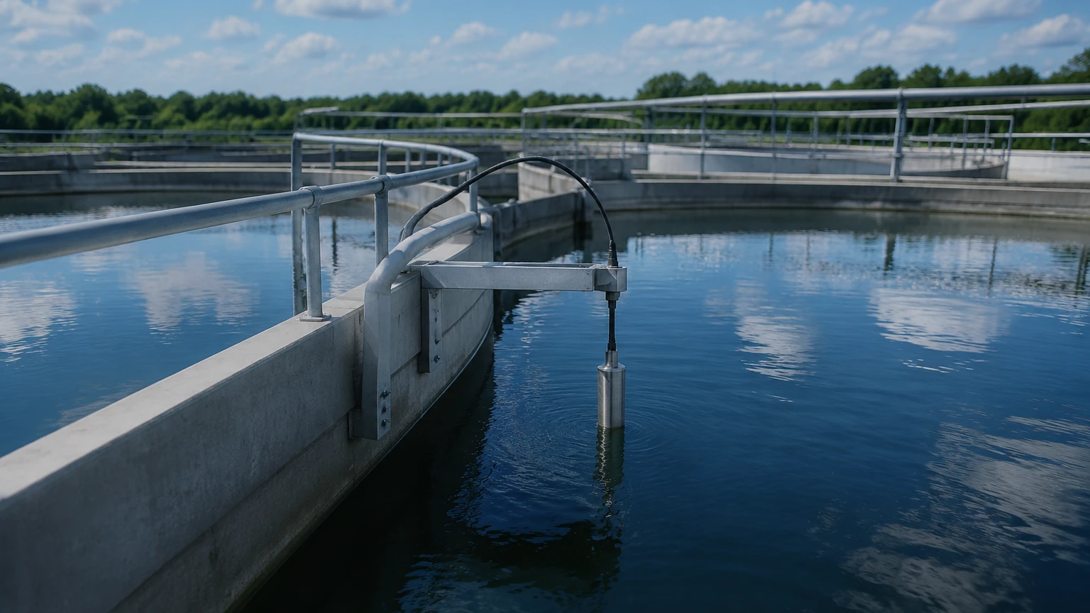
These are the most common type of hydrostatic tank sensors for deep wells, reservoirs, and open sumps. The sensor is housed in a waterproof (IP68) stainless steel or plastic casing and is lowered into the liquid by its own reinforced cable. The cable contains the electrical conductors as well as the atmospheric vent tube.
2. Externally Mounted Sensors
For tanks where the bottom is accessible from the outside, sensors can be mounted via threaded or flanged connections on the side or bottom of the vessel. These are often preferred in the chemical and food industries because they allow for easier maintenance without needing to empty the tank or pull a sensor out of the liquid. Diaphragm seals are often used here to protect the sensor from corrosive or high-temperature media.
3. Differential Pressure (DP) Transmitters
In closed, pressurized tanks (such as a boiler or a pressurized chemical reactor), the pressure above the liquid is not atmospheric. A standard hydrostatic sensor would fail here because it cannot distinguish between the liquid's weight and the gas pressure. A DP transmitter measures the pressure at both the bottom (high-pressure side) and the top (low-pressure side) of the tank. The difference between these two values represents the true hydrostatic head of the liquid.
Key Selection Criteria for Industrial Applications
Choosing the right sensor requires more than just knowing the tank height. Engineers must evaluate several variables to ensure long-term accuracy and reliability.
Liquid Density and Specific Gravity
Since hydrostatic pressure depends on density, any change in the liquid's Specific Gravity (SG) will affect the reading. If a sensor is calibrated for water (SG 1.0) but used in a diesel tank (SG 0.85), the level reading will be lower than the actual height. Many modern transmitters allow for density compensation in their internal software, but it is vital to confirm the fluid properties during the specification phase.
Chemical Compatibility
The wetted materials of the sensor must resist corrosion from the process media. Common materials include:
* 316L Stainless Steel: Standard for water and mild chemicals.
* Ceramic Diaphragms: Highly resistant to abrasion and many aggressive acids.
* PTFE/PVDF: Used for housings and cables in highly corrosive chemical storage.
Temperature Ranges
Temperature affects both the density of the liquid and the electronics of the sensor. High-quality hydrostatic tank sensors include internal temperature compensation to minimize thermal drift. However, for extreme temperatures, remote capillary seals may be required to isolate the electronics from the heat.
Selection Table for Hydrostatic Sensors
| Feature | Submersible Sensors | Externally Mounted (Threaded/Flanged) | Differential Pressure Transmitters |
| :— | :— | :— | :— |
| Best Use Case | Deep wells, sumps, open reservoirs | Process tanks, food & beverage | Pressurized vessels, boilers |
| Installation | Suspended by cable | Side-bottom nozzle | Dual-port piping |
| Maintenance | Requires pulling from top | Accessible from outside | Complex piping/valving |
| Pressure Type | Vented Gauge | Gauge or Absolute | Differential |
| Max Depth | Up to 200m+ (656 ft) | Limited by tank height | Limited by DP range |
Installation Best Practices and Considerations
Proper installation is critical to the performance of hydrostatic tank sensors. Failure to follow engineering guidelines can lead to signal instability or premature sensor failure.
1. Avoid Turbulence: Sensors should not be placed directly near an inlet pipe or an agitator. The kinetic energy of moving fluid can create localized pressure fluctuations that the sensor interprets as level changes. If turbulence is unavoidable, a stilling well (a perforated pipe) should be installed to shield the sensor.
2. Cable Management: For submersible models, the cable must be secured to prevent it from swinging. In deep applications, stainless steel support wires may be used to take the tension off the electrical cable. The vent tube at the end of the cable must be kept clear of moisture and debris; using a desiccant filter at the termination point is highly recommended.
3. Mounting Position: Externally mounted sensors should be placed at a point where sediment or sludge will not accumulate on the diaphragm. If the tank has a high solids content, mounting the sensor slightly above the very bottom of the tank can prevent clogging.
4. Zero and Span Calibration: After installation, it is necessary to calibrate the "zero" point (when the tank is empty or at the minimum measurable level) and the "span" point (at the maximum level). This ensures the 4-20mA signal accurately maps to the physical dimensions of the tank.
Limitations and Common Challenges
While hydrostatic tank sensors are versatile, they are not suitable for every application. Engineers should be aware of the following limitations:
* Variable Density: If a process involves mixing different liquids or if the temperature fluctuates wildly (causing density changes), the hydrostatic reading will drift unless real-time density compensation is implemented.
* Pressurized Vented Tanks: If a tank is supposed to be vented but the vent becomes blocked, the resulting internal pressure will cause significant errors in a standard gauge pressure sensor.
* Sediment Build-up: In wastewater applications, grease or sludge can coat the diaphragm. This increases the mass the diaphragm must move, leading to sluggish response or incorrect readings. Periodic cleaning or the use of flush-mounted diaphragms can mitigate this.
Maintenance and Calibration Procedures
To maintain high accuracy, a routine maintenance schedule should be established. For most industrial applications, a yearly calibration check is sufficient.
* Visual Inspection: Check for signs of corrosion on the housing and wear on the cable jacket. For submersible sensors, ensure the vent tube filter is not saturated with moisture.
* Cleaning: If the sensor is used in a coating or scaling liquid, gently clean the diaphragm with a soft cloth and a compatible solvent. Never use sharp objects to clean a pressure diaphragm, as they are extremely thin and easily damaged.
* Signal Verification: Use a calibrated pressure source to simulate levels and verify that the output (e.g., 4-20mA) matches the expected values. For comprehensive product support and technical documentation on calibration, you can visit the Main Page to review product options and application support.
Frequently Asked Questions
Q: Can hydrostatic sensors be used for solids?
No. Hydrostatic sensors rely on the fluid properties of liquids to transmit pressure equally in all directions. Bulk solids do not behave this way and will not provide an accurate reading.
Q: What is the maximum cable length for a submersible sensor?
While the electronic signal (4-20mA) can travel hundreds of meters, the physical limitation is often the tensile strength of the cable and the ability to maintain a clear vent path. Most industrial manufacturers offer cable lengths up to 500 meters (1,640 ft) for specialized deep-well applications.
Q: How does a hydrostatic sensor handle foam?
One of the advantages of hydrostatic technology is that it is largely unaffected by foam. Since foam has very low density, it does not exert significant pressure on the sensor. The sensor will measure the "true" liquid level beneath the foam, unlike ultrasonic or radar sensors which might reflect off the top of the foam layer.
Q: Is lightning protection necessary?
For sensors installed in outdoor tanks or deep wells, lightning strikes can induce high-voltage surges in the cable. Selecting sensors with built-in surge protection or installing external lightning arrestors is a standard best practice for these environments.
By following these technical guidelines and selecting the appropriate hardware for the specific media and container type, hydrostatic tank sensors provide a cost-effective and durable solution for industrial level monitoring. For further technical specifications and to explore the full range of measurement instruments, visit the Welk Main Page.