Pressure Level Transducer
Pressure Level Transducer
In the field of industrial process control, the pressure level transducer—often referred to as a hydrostatic level transmitter—remains one of the most reliable and widely adopted technologies for monitoring liquid levels. By measuring the force exerted by a liquid column under the influence of gravity, these instruments provide a direct correlation to the height of the fluid in a tank, well, or reservoir. This guide explores the engineering principles, selection criteria, and practical installation requirements for pressure-based level measurement.
Measurement Principles of Hydrostatic Pressure
The operation of a pressure level transducer is based on the physical law of hydrostatics. The pressure at a specific point in a static fluid is determined by the height of the liquid column above that point, the density of the fluid, and the force of gravity. This relationship is expressed by the formula:
P = ρ × g × h
Where:
* P is the hydrostatic pressure (measured in Pascals or bar).
* ρ (rho) is the density of the liquid (kg/m³).
* g is the local acceleration due to gravity (approximately 9.81 m/s²).
* h is the height of the liquid column (meters).
Because gravity is constant and the density of many industrial fluids (like water) remains relatively stable, the pressure measured by the transducer is directly proportional to the liquid level. For example, in a water tank, every 1 meter (3.28 ft) of depth generates approximately 9.81 kPa (0.098 bar or 1.42 psi) of pressure.
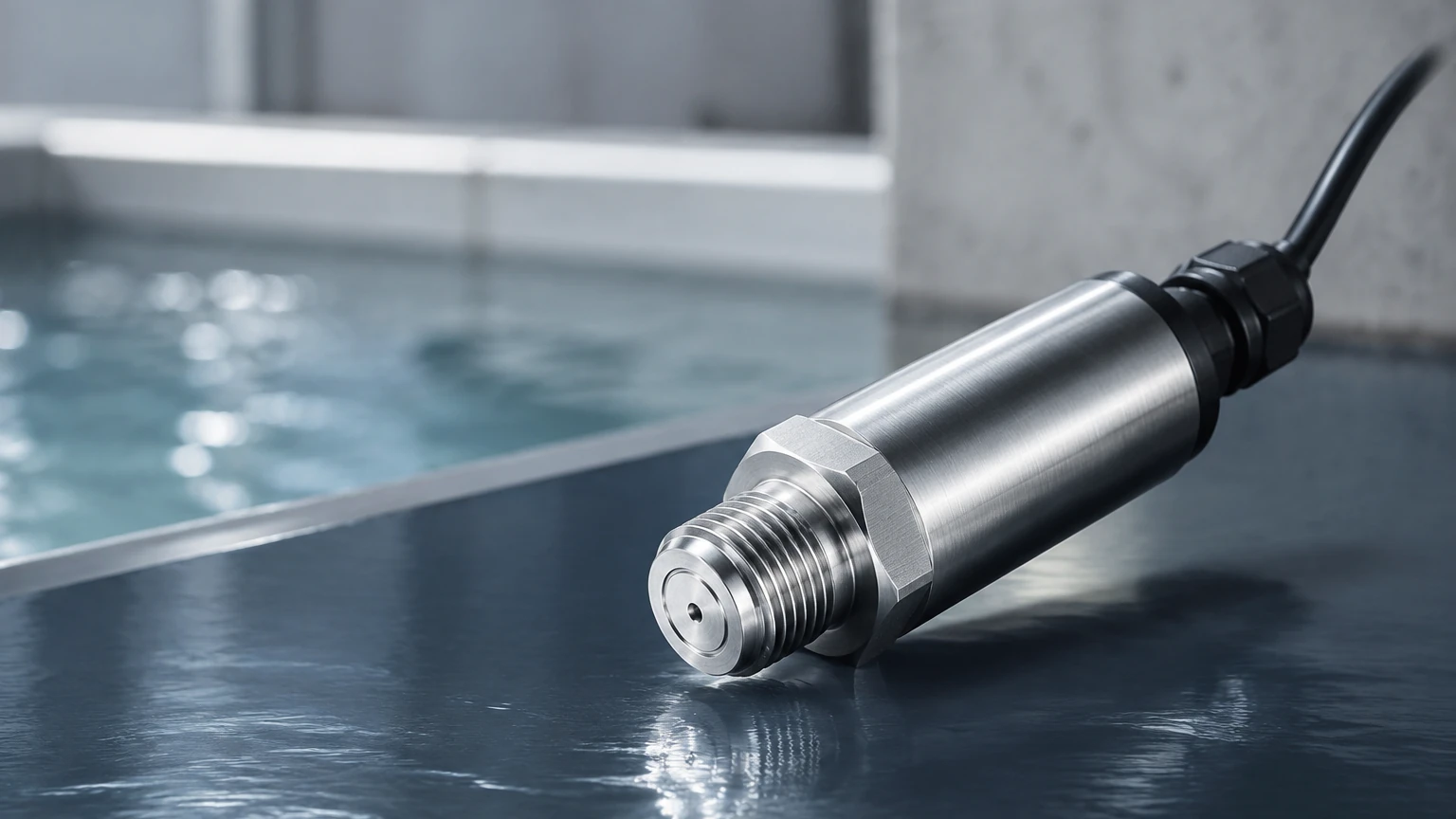
A pressure level transducer typically utilizes a sensing element—such as a piezoresistive silicon sensor or a ceramic capacitive cell—protected by a flexible diaphragm. As the liquid level rises, the increasing pressure compresses the diaphragm, which in turn changes the electrical resistance or capacitance of the sensor. The internal electronics then convert this physical change into a standardized industrial signal, such as 4-20mA, 0-10V, or a digital protocol like RS485 Modbus.
Types of Pressure Level Transducers
Selecting the correct instrument requires understanding the two primary configurations used in industrial automation: submersible and external (threaded/flanged) transducers.
Submersible Level Transducers
These instruments are designed to be lowered directly into the liquid. They are commonly used in deep wells, boreholes, open reservoirs, and wastewater lift stations. The transducer housing is hermetically sealed (usually IP68 rated) and made from corrosion-resistant materials like 316L stainless steel or Titanium. A critical feature of the submersible model is the vented cable, which contains a small capillary tube that allows the sensor to reference atmospheric pressure, ensuring that changes in barometric pressure do not affect the level reading.
External Pressure Transducers
External transducers are mounted to the outside of a vessel via a threaded or flanged process connection at the lowest point of measurement. These are ideal for process tanks where the instrument must be accessible for maintenance without entering the vessel. In applications involving viscous fluids or food-grade requirements, flush diaphragm models are used to prevent clogging or bacterial growth in the sensor cavity.
Selection Criteria and Technical Considerations
Choosing the right pressure level transducer involves more than just selecting a depth range. Engineers must evaluate several environmental and chemical factors to ensure long-term reliability.
1. Media Compatibility
The wetted materials must be chemically compatible with the liquid. While 316L stainless steel is standard for water and light oils, aggressive chemicals may require PTFE (Teflon) coatings, Hastelloy, or ceramic diaphragms. For wastewater applications, a large-diameter diaphragm is often preferred to prevent fouling from suspended solids.
2. Pressure Range and Accuracy
It is best practice to select a transducer with a range slightly higher than the maximum expected liquid level. If a tank is 5 meters (16.4 ft) deep, a 0-6 meter (0-0.6 bar) range provides a safety margin and optimal resolution. Accuracy is typically expressed as a percentage of the Full Scale (FS), with standard industrial models offering ±0.5% FS and high-precision models reaching ±0.1% FS.
3. Temperature Range
Fluctuations in temperature can affect the density of the liquid and the performance of the sensor electronics. Most high-quality transducers include internal temperature compensation to mitigate these effects within a specified range (e.g., -10°C to +80°C). For high-temperature steam or chemical processes, cooling spacers or remote capillary seals may be necessary.
Comparison Table: Submersible vs. External Transducers
| Feature | Submersible Transducer | External (Threaded/Flanged) |
| :— | :— | :— |
| Best Use Case | Deep wells, open reservoirs, sumps | Process tanks, pressurized vessels |
| Installation | Suspended by cable | Mounted to pipe or tank wall |
| Maintenance | Requires pulling the unit up | Accessible from outside |
| Venting | Integrated capillary in cable | Atmospheric or differential port |
| Clogging Risk | Moderate (minimized by cage) | High (minimized by flush diaphragm) |
| Typical Materials | 316L SS, PVC, Titanium | 316L SS, Hastelloy, Ceramic |
Installation Guidelines for Reliable Performance
Correct installation is paramount to preventing signal drift and mechanical failure. For a comprehensive look at available hardware and technical support, engineers can Review product options and application support to match specific site requirements.
Mechanical Mounting
* Submersible Units: In applications with high turbulence or flow (such as an agitated tank), the transducer should be installed inside a stilling well (a perforated pipe) to prevent the unit from swinging, which can cause mechanical fatigue on the cable and erratic readings.
* External Units: Ensure the transducer is installed at or below the "zero" level of the tank. If the sensor is installed 10 cm above the bottom, it will not be able to measure the final 10 cm of fluid.
Atmospheric Compensation
For submersible sensors, the vented cable must terminate in a dry environment. A moisture filter or desiccant cartridge should be attached to the end of the vent tube to prevent water vapor from entering the transducer housing, which could cause internal corrosion or sensor failure.
Electrical Protection
Since many pressure level transducers are installed in outdoor or industrial environments, they are susceptible to lightning strikes and power surges. Using a shielded cable and ensuring the shield is grounded at the controller end (not both ends, to avoid ground loops) is essential. In hazardous areas, intrinsically safe (IS) barriers must be used in conjunction with ATEX or IECEx certified sensors.
Limitations and Potential Risks
While highly versatile, pressure level transducers have specific limitations that must be managed:
1. Density Sensitivity: Since the measurement is based on weight, any change in the liquid's density (caused by temperature changes or mixing different chemicals) will result in a level error. If the density decreases, the pressure decreases, and the sensor will report a lower level than actually exists.
2. Pressurized Tanks: In a closed, pressurized vessel, the sensor at the bottom measures both the liquid pressure and the gas pressure above the liquid. In these cases, a differential pressure (DP) transducer is required to subtract the top-side pressure from the total pressure.
3. Mechanical Damage: Diaphragms are thin and sensitive. Dropping a submersible sensor or poking the diaphragm with a tool during cleaning can permanently damage the calibration or rupture the seal.
Troubleshooting Common Issues
* Constant 4mA or 0V Output: This often indicates a total loss of power or a broken wire in the loop. Check the power supply and cable continuity.
* Reading Drifts Over Time: This is frequently caused by moisture entering the vent tube of a submersible cable. Check the desiccant and ensure the vent tube is not kinked or blocked.
* Inaccurate Readings in Agitated Tanks: If the sensor is not in a stilling well, the kinetic energy of the moving fluid can create localized pressure zones, leading to unstable data.
Frequently Asked Questions (FAQ)
Q: Can a pressure level transducer measure the level of foam?
A: Generally, no. Pressure transducers measure the weight of the liquid. Foam is mostly air and has very little mass, so the transducer will measure the level of the liquid phase and ignore the foam layer. This is often an advantage over ultrasonic sensors, which may struggle with foam interference.
Q: How often should the sensor be calibrated?
A: For most industrial applications, an annual calibration check is sufficient. However, in critical chemical processes or high-accuracy custody transfer applications, semi-annual checks may be required.
Q: What is the maximum depth a submersible transducer can measure?
A: Standard models can handle up to 200 meters (approx. 650 ft) of water column, but specialized deep-well transducers are available for much greater depths, often used in groundwater monitoring and mining.
Q: Is it possible to use a pressure level transducer for oil and water interface?
A: A single pressure transducer cannot distinguish between two different liquids; it only measures the total hydrostatic head. Measuring an interface typically requires other technologies, such as guided wave radar or specialized capacitive probes.
By understanding the physical relationship between pressure and depth, and by carefully selecting materials and installation methods, engineers can implement pressure level transducers as a cost-effective and highly accurate solution for a vast range of industrial level measurement challenges.