API 2350 5th Edition Sensor Independence Category 3
API 2350 5th Edition Sensor Independence Category 3
In the realm of industrial tank farm management, the American Petroleum Institute (API) Standard 2350 serves as the definitive guideline for overfill protection for atmospheric storage tanks. With the release of the 5th edition, the standard has further refined the requirements for safety, shifting toward a more rigorous risk-based approach that aligns with functional safety standards like IEC 61511. Central to this framework is the concept of "Category 3" facilities, which demand the highest level of automated protection. Understanding the nuances of api 2350 5th edition sensor independence category 3 is essential for engineers and safety managers tasked with mitigating the environmental and financial risks of tank overfills.
The Evolution of API 2350 and the Role of Category 3
API 2350 was developed to prevent overfill incidents in tanks receiving Class I and Class II flammable and combustible liquids. The 5th edition emphasizes the "Safety Lifecycle," requiring operators to conduct formal risk assessments to determine the necessary level of protection.
The standard classifies tank installations into three categories based on the level of automation and the presence of personnel during receipt operations:
1. Category 1: Fully manual operations where a person is physically present to monitor the level and terminate the receipt.
2. Category 2: Semi-automated systems featuring an Automatic Tank Gauge (ATG) and a High-Level Alarm (HLA) that alerts personnel to take action.
3. Category 3: Fully automated systems where an independent Overfill Prevention System (OPS) is required to terminate the flow automatically or provide a redundant, independent alarm to a constantly attended location.
For Category 3 tanks, the standard mandates a strict separation between the Tank Gauging System (TGS) used for inventory and the Overfill Prevention System (OPS). This separation is defined as sensor independence.
Core Measurement Principles for Overfill Protection
Before selecting hardware for a Category 3 system, it is vital to understand the underlying measurement principles. Reliability in an overfill scenario depends on the sensor's ability to detect the liquid level accurately under emergency conditions, which may involve turbulence, foam, or rapid temperature changes.
Radar Level Measurement (FMCW and Pulse)
Radar transmitters operate by emitting electromagnetic waves toward the liquid surface. In Frequency Modulated Continuous Wave (FMCW) radar, the device emits a continuous signal with a varying frequency. The difference in frequency between the emitted and received signal is proportional to the distance. Pulse radar, conversely, measures the time-of-flight of a microwave pulse. Radar is highly preferred for API 2350 applications because it is non-contact, meaning the electronics are not exposed to the corrosive or viscous nature of the stored media.
Guided Wave Radar (GWR)
GWR utilizes a physical probe (rod or cable) to guide the microwave signal to the liquid surface. This principle is based on Time Domain Reflectometry (TDR). When the signal hits a medium with a different dielectric constant than air, a portion of the energy is reflected. GWR is exceptionally stable in tanks with heavy foam or steam, making it a robust choice for independent high-high level alarms (HHLA).
Ultrasonic Level Sensors
Ultrasonic sensors emit high-frequency sound waves. The time taken for the echo to return is used to calculate the distance. While cost-effective, these are generally limited to stable environments. In petroleum applications, vapors and temperature gradients can change the speed of sound, potentially leading to inaccuracies. Therefore, they are less common in Category 3 OPS compared to radar.
Vibrating Tuning Fork (Point Level)
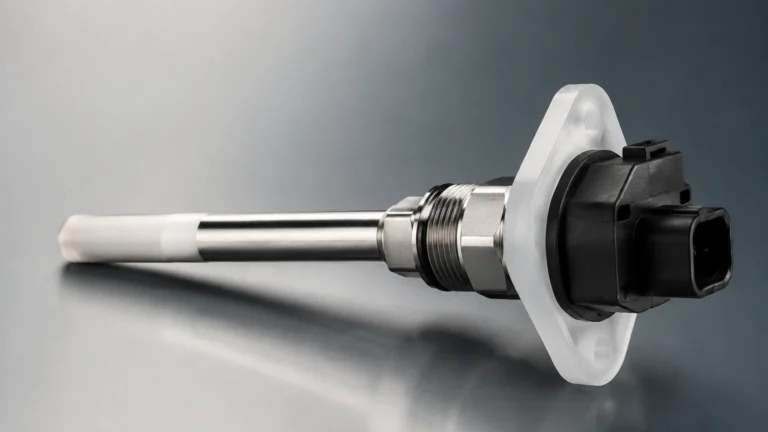
This is a frequency-based principle. A tuning fork vibrates at its natural resonance frequency in air. When submerged in liquid, the frequency shifts. This shift is detected by the electronics and converted into a switching signal. Because they are "fail-safe" (a broken fork or lost power triggers an alarm), they are the industry standard for independent point-level detection in Category 3 systems.
Defining Sensor Independence in Category 3 Systems
The core requirement of api 2350 5th edition sensor independence category 3 is that the failure of the inventory system (TGS) must not compromise the overfill prevention system (OPS). This independence is categorized into physical, electrical, and functional layers.
Physical Independence
In a Category 3 installation, the OPS sensor must be a separate physical device from the TGS sensor. This typically means the sensors are mounted on different tank nozzles. If a single nozzle must be used due to tank design constraints, the sensors must still be separate units (e.g., a radar for inventory and a tuning fork for the high-high alarm) to ensure that a mechanical blockage or localized turbulence at that nozzle doesn't disable both systems simultaneously.
Electrical and Logic Independence
Independence extends beyond the sensor. The wiring, power supply, and logic solver (PLC or DCS) should ideally be separate. In many high-risk Category 3 applications, the OPS is integrated into a Safety Instrumented System (SIS) with a dedicated logic solver that is independent of the Basic Process Control System (BPCS) used for daily inventory management. This prevents a software crash or processor failure in the inventory system from affecting the emergency shutdown capability.
The "Proof Testing" Requirement
The 5th edition places heavy emphasis on the ability to test these independent sensors. A sensor that cannot be tested is not considered reliable. Modern systems often include "remote proof-test" capabilities, allowing operators to verify the functionality of the HHLA without climbing the tank or manually raising the liquid level.
Technology Selection Table for API 2350 Compliance
When designing a Category 3 system, engineers must match the technology to the specific risks of the media and the tank geometry. The following table provides a comparison of common technologies used for independent overfill protection.
| Technology | Measurement Type | API 2350 Suitability | Advantages | Limitations |
| :— | :— | :— | :— | :— |
| Non-Contact Radar | Continuous | High (Primary or Backup) | No contact with media; high accuracy; handles vapors well. | Higher initial cost; requires clear line of sight. |
| Guided Wave Radar | Continuous | High (Primary or Backup) | Not affected by foam or turbulence; very reliable. | Probe can accumulate buildup; requires contact with liquid. |
| Vibrating Tuning Fork | Point Level | Excellent (HHLA) | Fail-safe design; easy to test; unaffected by foam/bubbles. | Only provides a single point of detection; no inventory data. |
| Magnetic Level Gauge | Visual/Point | Moderate | No power required for visual check; clear local indication. | Mechanical parts can stick; requires side-mounting bypass. |
| Float Switches | Point Level | Low/Moderate | Simple and inexpensive. | High maintenance; prone to mechanical failure/sticking. |
| Hydrostatic Pressure | Continuous | Moderate | Good for vented tanks; easy installation. | Accuracy depends on constant fluid density. |
For comprehensive product specifications and engineering support for these technologies, you can visit our Main Page.

Installation Guidelines for Independent Sensors
Proper installation is as critical as sensor selection for maintaining Category 3 compliance. Even the most advanced radar sensor will fail if installed incorrectly.
1. Nozzle Placement: The independent OPS sensor should be located away from the fill pipe to avoid "nuisance alarms" caused by splashing or turbulence during receipt.
2. Stilling Wells: For tanks with internal obstructions or heavy agitation, installing the independent sensor (especially GWR or radar) inside a stilling well (typically 100 mm to 200 mm in diameter) can provide a calm surface for more accurate measurement.
3. The "Dead Zone": Every sensor has a blocking distance or dead zone at the top of its range. For overfill protection, the sensor must be mounted high enough that the maximum required alarm level (the High-High level) is outside this dead zone.
4. Redundancy vs. Independence: It is important to distinguish between the two. Redundancy is having two of the same thing. Independence is having two systems that do not share a common mode of failure. For Category 3, focus on independence.
Limitations and Risk Mitigation
While api 2350 5th edition sensor independence category 3 significantly reduces the risk of overfills, certain limitations remain:
* Common Cause Failures: If both the TGS and OPS sensors are of the same type and from the same manufacturer, a systematic software bug or a specific environmental condition (e.g., extreme icing) might affect both. Using diverse technologies (e.g., Radar for TGS and Tuning Fork for OPS) mitigates this.
* Human Factors: Even an automated Category 3 system can be bypassed. The 5th edition requires administrative controls to ensure that safety systems are not inhibited during active transfers.
* Response Time: The system must be designed with a response time that accounts for the maximum fill rate. The High-High alarm must be set at a level that allows valves to close fully before the tank reaches its critical high level (the point where structural damage or spill occurs).
Frequently Asked Questions
Q: Can I use a single multi-variable transmitter for both inventory and overfill protection in Category 3?
A: Generally, no. API 2350 5th Edition emphasizes sensor independence. A single transmitter, even if it has two separate electronic outputs, represents a single point of failure. If the probe or the primary electronics fail, both functions are lost.
Q: Does Category 3 require a Safety Integrity Level (SIL) rating?
A: While API 2350 does not strictly mandate a specific SIL level, it points toward a risk-based approach. Many operators find that to meet the risk reduction requirements of a Category 3 tank, a SIL 2 rated system is the most practical solution.
Q: How often should independent sensors be proof-tested?
A: The 5th edition moves away from fixed intervals to a schedule based on the manufacturer's recommendations and the facility's specific risk assessment. However, annual testing is a common industry baseline.
Q: Is a manual gauge tape considered an independent sensor?
A: No. For Category 3, the overfill prevention must be part of an automated system. Manual gauging is a component of Category 1 or a secondary check for Category 2, but it does not meet the automated requirements of Category 3.
Conclusion
Compliance with api 2350 5th edition sensor independence category 3 is a cornerstone of modern terminal safety. By ensuring that the overfill prevention system is physically and functionally separate from inventory management, operators can significantly reduce the probability of catastrophic spills. Selecting the right measurement principle—whether it be non-contact radar for continuous monitoring or vibrating tuning forks for fail-safe point detection—requires a deep understanding of both the standard and the specific application environment. Through rigorous engineering, proper installation, and regular proof testing, the goals of API 2350 can be met, protecting personnel, assets, and the environment.
Download API 2350 5th Edition Sensor Independence Category 3 as a PDF