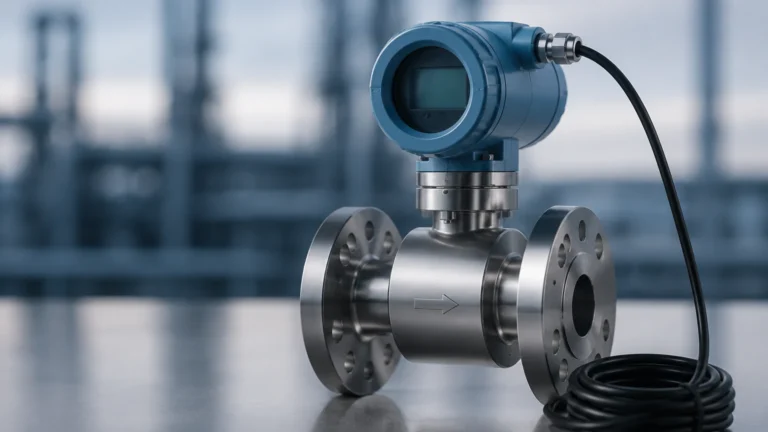
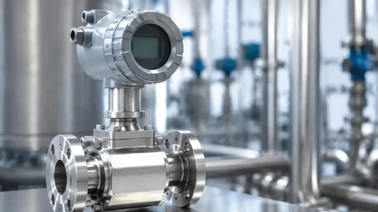
Coriolis Flow Meter How It Works
Coriolis Flow Meter How It Works
In the landscape of industrial process control, the ability to measure fluid mass with high precision is often the difference between a high-quality product and a wasted batch. While many flow measurement technologies rely on volume—which can fluctuate based on temperature and pressure—the Coriolis flow meter provides a direct measurement of mass. This article explores the technical foundations of the Coriolis flow meter, how it works, and how to select and install these instruments in demanding B2B environments.
Understanding the mechanics of these devices is essential for engineers and procurement specialists who require reliable data for custody transfer, chemical dosing, and complex blending applications. As a professional manufacturer of industrial measurement instruments, Welk provides this guide to assist in the technical evaluation of mass flow technology alongside our range of level measurement solutions.
The Fundamental Principle of Mass vs. Volume
Before diving into the mechanics of the Coriolis effect, it is important to distinguish between mass flow and volumetric flow. Volumetric flow meters measure the space a fluid occupies (e.g., liters per minute). However, fluids—especially gases and compressed liquids—change volume when temperature or pressure shifts. Mass, conversely, remains constant regardless of environmental changes.
Because Coriolis meters measure mass directly, they eliminate the need for secondary compensation calculations for temperature and pressure, which are often required for vortex or turbine meters. This inherent accuracy makes them the gold standard for high-value fluids.
Coriolis Flow Meter How It Works: The Physics of Oscillation
The operation of a Coriolis flow meter is based on the principles of motion and the Coriolis force. Named after the French physicist Gaspard-Gustave de Coriolis, the effect describes the inertial force acting on objects in motion within a rotating frame of reference.
1. Tube Vibration
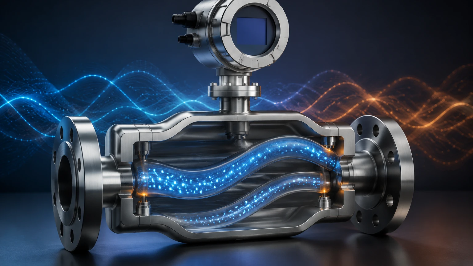
In a Coriolis meter, the fluid passes through one or two vibrating tubes. An internal drive coil causes the tubes to oscillate at their natural resonant frequency. This vibration is typically very small in amplitude (less than 1 mm) and high in frequency (up to 1000 Hz).
2. The Coriolis Effect in Action
When there is no flow, the tubes vibrate uniformly. However, when fluid begins to move through the tubes, the Coriolis force is generated. As the fluid moves toward the point of maximum vibration (the center of the tube), it resists being pushed upward and exerts a downward force on the tube. As the fluid moves away from the center toward the outlet, it resists having its vertical motion slowed down and exerts an upward force.
3. Phase Shift Detection
This opposing force causes the vibrating tube to twist. This twisting motion is known as a "phase shift." Sensors (pick-off coils) located at the inlet and outlet sides of the tube record the oscillation.
* Zero Flow: The inlet and outlet sine waves are perfectly in sync.
* Active Flow: The inlet and outlet sine waves are shifted relative to each other.
The time delay (delta-T) between these two sine waves is directly proportional to the mass flow rate. The greater the mass of the fluid and the faster it moves, the greater the twist and the resulting phase shift.
Simultaneous Density and Temperature Measurement
One of the most significant advantages of the Coriolis flow meter is its ability to measure multiple variables simultaneously.
Density Measurement
The resonant frequency at which the tubes vibrate is dependent on the total mass of the system (the mass of the tubes plus the mass of the fluid inside them). Since the mass of the tubes is constant, any change in the resonant frequency is caused by a change in the density of the fluid. By measuring this frequency, the transmitter can calculate the fluid's density in real-time.
Temperature Measurement
To ensure the highest accuracy, Coriolis meters include an internal Resistance Temperature Detector (RTD). This sensor monitors the temperature of the flow tubes. Because the elasticity of the metal tubes changes slightly with temperature, the transmitter uses this data to compensate for mechanical changes in the tube structure, ensuring the mass flow and density readings remain precise.
For those looking to integrate these sophisticated flow measurements with advanced level monitoring, you can Review product options and application support on our main site to see how these technologies complement each other in industrial automation.
Key Components of a Coriolis System
A standard Coriolis flow meter system consists of two primary elements: the sensor and the transmitter.
1. The Sensor: This is the wetted part of the instrument. It includes the flow tubes (U-shaped, straight, or curved), the drive coil that initiates vibration, and the pick-off sensors that detect the phase shift.
2. The Transmitter: This is the "brain" of the meter. It provides the power to the drive coil, processes the raw electronic signals from the pick-off sensors, and converts them into usable data (mass flow, density, and temperature). It also handles communication protocols like 4-20mA HART, Modbus, or Profibus.
Practical Selection Table for Coriolis Flow Meters
Choosing the right tube geometry is critical for balancing accuracy and pressure drop. The following table summarizes the common configurations found in industrial applications.
| Tube Geometry | Primary Advantages | Common Applications | Limitations |
| :— | :— | :— | :— |
| U-Shaped Tube | Extremely high sensitivity; excellent for low flow rates. | Chemical dosing, high-precision laboratory work. | Higher pressure drop; prone to fluid trapping if not oriented correctly. |
| Straight Tube | Low pressure drop; easy to clean (CIP/SIP); compact. | Food and beverage, pharmaceutical, viscous fluids. | Less sensitive to very low flows; more affected by temperature extremes. |
| Dual-Tube | Balanced vibration reduces external noise interference. | General industrial use, oil and gas custody transfer. | Larger physical footprint than single-tube designs. |
| Micro-bend | Balance between U-shape and straight; compact. | OEM machinery, space-constrained skids. | Moderate pressure drop. |
Installation Considerations and Best Practices
While Coriolis meters are highly accurate, their performance is heavily dependent on proper installation. Because the measurement relies on detecting minute vibrations, external factors can introduce error.
1. Vibration Isolation
The meter should be installed in a location free from significant mechanical vibration. High-frequency vibrations from nearby pumps or heavy machinery can interfere with the drive coil's frequency. Using flexible connectors or robust pipe supports on either side of the meter is recommended.
2. Orientation and Fluid State
To ensure accuracy, the tubes must remain full of fluid.
* For Liquids: Install the meter in a low point of the piping or in a vertical upward-flow position to prevent air bubbles from becoming trapped. Entrained gas can cause "slug flow," which significantly disrupts the vibration signals.
* For Gases: Install the meter in a high point or vertical downward-flow position to prevent condensate (liquids) from accumulating in the tubes.
3. Stress-Free Mounting
The meter should not be used to support the weight of the piping. Misalignment or mechanical stress on the meter body can distort the flow tubes, leading to a "zero shift" error. Always ensure the piping is properly aligned before bolting the flanges.
4. Zero Calibration
After installation and once the system is filled with the process fluid at operating temperature and pressure, a "zero trim" must be performed. This involves closing valves on both sides of the meter to ensure a state of absolute zero flow, allowing the transmitter to calibrate its baseline.
Limitations and Technical Challenges
Despite their versatility, Coriolis flow meters are not a universal solution for every application. Engineers should be aware of the following limitations:
* Initial Cost: Coriolis meters are generally more expensive than magnetic or ultrasonic meters. The investment is typically justified by the reduction in maintenance and the elimination of secondary sensors.
* Size Constraints: For very large pipe diameters (above 300 mm), Coriolis meters become extremely heavy, bulky, and prohibitively expensive.
* Pressure Drop: U-shaped designs can cause a significant pressure drop in the system, which may require larger pumps or higher energy consumption.
* Entrained Gas: While modern digital signal processing (DSP) has improved performance in two-phase flow, high concentrations of gas bubbles in a liquid stream can still cause the meter to "stall" or lose accuracy.
Frequently Asked Questions (FAQs)
Can Coriolis meters measure steam?
Coriolis meters are generally not recommended for steam measurement. The low density and high velocity of steam make it difficult for the tubes to generate a measurable Coriolis force. Vortex flow meters are typically a better choice for steam applications.
Do Coriolis meters require a straight run of pipe?
Unlike most other flow technologies (like turbine or orifice plates), Coriolis meters do not require long straight runs of pipe before or after the meter. They are unaffected by flow profiles or turbulence, making them ideal for tight installations.
How often do they need calibration?
Because they have no moving parts to wear out, Coriolis meters are incredibly stable. In many non-corrosive applications, they can remain in service for years without a shift in calibration. However, for custody transfer applications, annual verification is often required by local regulations.
Can they measure non-conductive fluids?
Yes. Unlike magnetic flow meters, which require the fluid to be conductive, Coriolis meters work on any fluid with mass, including deionized water, oils, and hydrocarbons.
Conclusion
Understanding a Coriolis flow meter and how it works allows process engineers to leverage one of the most accurate and reliable measurement technologies available today. By providing direct mass flow, density, and temperature in a single device, these meters simplify system architecture and reduce the margin for error in critical processes.
When selecting instrumentation for your facility, it is vital to consider how flow and level measurements interact to provide a complete picture of your inventory and process efficiency. For more information on professional-grade measurement solutions, visit our Main Page to explore our comprehensive range of industrial sensors and transmitters designed for the modern automated environment.