Ultrasonic Clamp on Flow Meter
Ultrasonic Clamp on Flow Meter
In the landscape of industrial process control, the ability to measure fluid velocity without breaching the integrity of the piping system is a significant technological advantage. The ultrasonic clamp on flow meter has emerged as a primary solution for facilities seeking to upgrade their monitoring capabilities without the downtime or leakage risks associated with traditional inline meters. As a professional manufacturer of industrial measurement instruments, Welk provides these solutions to industries ranging from water treatment to chemical processing, ensuring that accuracy and reliability are maintained even in the most demanding environments.
This guide provides a comprehensive technical overview of ultrasonic flow measurement technology, detailing how these devices function, how to select the appropriate model for specific applications, and the critical installation factors that determine long-term performance.
Understanding the Measurement Principles
Before selecting an ultrasonic clamp on flow meter, it is essential to understand the two primary physical principles used to derive flow data: Transit-Time and Doppler Effect. While both utilize ultrasonic transducers clamped to the exterior of the pipe, they are suited for different fluid characteristics.
Transit-Time Method
The transit-time principle is the most common method used in industrial applications, particularly for clean liquids. This technology utilizes a pair of transducers that function as both transmitters and receivers. They are mounted on the pipe at a specific distance from each other.
The meter sends ultrasonic pulses back and forth between the two transducers. When the fluid is moving, the pulse traveling in the direction of the flow (downstream) moves faster than the pulse traveling against the flow (upstream). The difference in these transit times is directly proportional to the velocity of the liquid. By integrating this velocity with the internal cross-sectional area of the pipe, the meter calculates the volumetric flow rate. This method is highly accurate for liquids with less than 2% total suspended solids (TSS) or entrained air.
Doppler Effect Method
The Doppler effect method is used when the liquid contains a significant amount of particles, bubbles, or suspended solids. In this configuration, a transducer transmits an ultrasonic signal into the fluid at a known frequency. This signal reflects off the moving particles or bubbles within the liquid.
Because the reflectors are moving, the frequency of the reflected signal is shifted (the Doppler shift). The flow meter measures this frequency shift to determine the velocity of the fluid. While generally less precise than transit-time meters in clean water, Doppler meters are indispensable for wastewater, slurries, and aerated liquids where transit-time signals would be scattered or absorbed.
Key Advantages of Non-Invasive Flow Measurement
The adoption of the ultrasonic clamp on flow meter is driven by several operational benefits that inline technologies, such as magnetic or turbine meters, cannot provide:
1. Zero Pressure Drop: Because there are no components protruding into the flow stream, the meter does not cause any energy loss or pressure drop within the system.
2. No Process Downtime: Installation occurs on the exterior of the pipe. There is no need to shut down the process, drain the pipes, or cut into the infrastructure.
3. Chemical Compatibility: Since the sensors never touch the process fluid, there is no risk of corrosion or chemical attack on the instrument. This makes them ideal for high-purity water or aggressive acids.
4. Leak Prevention: By maintaining the integrity of the pipe wall, the risk of leaks at flange points or sensor seals is entirely eliminated.
5. Portability: Many ultrasonic units are available in handheld configurations, allowing technicians to verify the performance of existing inline meters or conduct temporary flow surveys across a facility.
For engineers looking to integrate these flow solutions with existing level monitoring systems, reviewing product options and application support on the Welk Main Page can provide a holistic view of available industrial instrumentation.
Selection Criteria for Industrial Applications
Selecting the right ultrasonic clamp on flow meter requires a detailed analysis of the application environment. Engineers must confirm several technical parameters to ensure the device will provide reliable data.
Pipe Material and Liner
Ultrasonic waves must pass through the pipe wall to reach the fluid. The material of the pipe (e.g., carbon steel, stainless steel, PVC, ductile iron) significantly affects signal attenuation. Furthermore, if the pipe has an internal liner (such as cement, rubber, or glass), the thickness and material of that liner must be known. If there is an air gap between the liner and the pipe wall, the ultrasonic signal will be blocked, rendering the meter inoperable.
Fluid Properties
As discussed in the principles section, the cleanliness of the fluid dictates whether a transit-time or Doppler meter is required. Additionally, the sonic velocity of the fluid (which varies with temperature and concentration) must be programmed into the meter. Most modern meters include a library of common fluids, but custom mixtures may require manual calibration.
Temperature Ranges
Standard transducers typically operate up to 80°C (176°F). For high-temperature applications, such as boiler feed water or hot oil, specialized high-temperature transducers and high-viscosity coupling compounds are required to withstand temperatures up to 250°C (482°F) or higher.
Selection Reference Table
| Feature | Transit-Time Meter | Doppler Effect Meter |
| :— | :— | :— |
| Primary Application | Clean liquids, potable water, oils | Wastewater, slurries, aerated liquids |
| Suspended Solids | < 2% by volume | > 100 ppm of particles > 75 microns |
| Accuracy | ±0.5% to ±2.0% of rate | ±2.0% to ±5.0% of full scale |
| Pipe Size Range | 15 mm to 6000 mm (0.5" to 240") | 25 mm to 5000 mm (1.0" to 200") |
| Sensitivity to Bubbles | High (can cause signal loss) | Required for measurement |
Installation Requirements and Mounting Methods
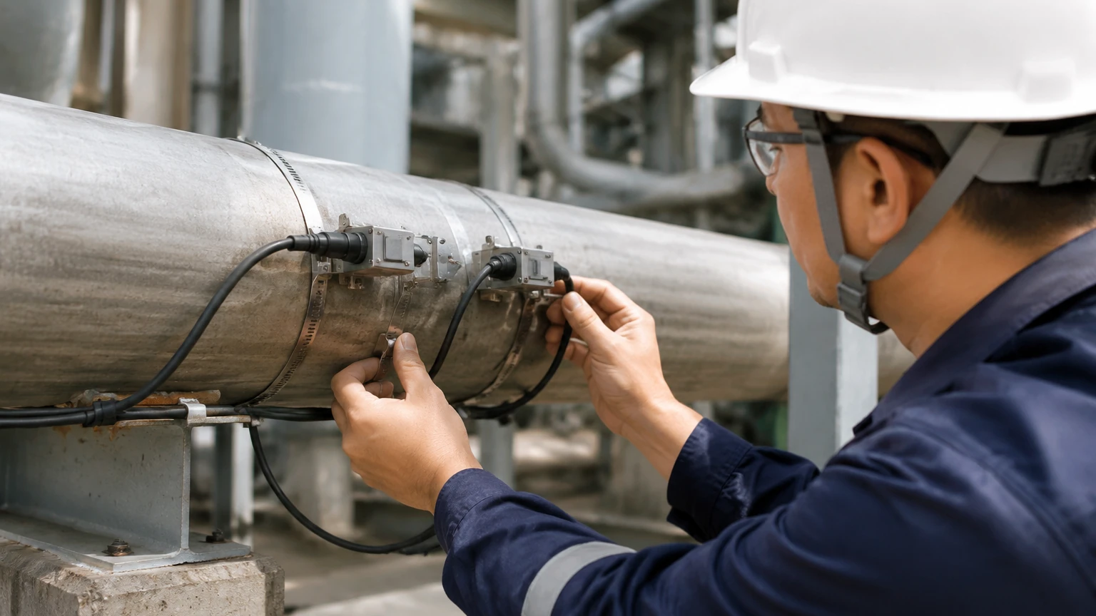
The accuracy of an ultrasonic clamp on flow meter is heavily dependent on the quality of the installation. Unlike inline meters, where the manufacturer controls the flow geometry, clamp-on meters rely on the user to identify a suitable location.
Straight Pipe Requirements
To ensure a stable and predictable flow profile, the meter must be installed on a straight section of pipe. The general rule of thumb is "10D Upstream and 5D Downstream." This means there should be a straight pipe length equal to 10 times the pipe diameter before the meter and 5 times the diameter after it. Obstructions such as pumps, valves, and elbows create turbulence that can distort the ultrasonic signal and lead to inaccurate readings.
Transducer Mounting Configurations
There are three primary methods for mounting transducers, depending on the pipe size and fluid characteristics:
* V-Method: The most common method for pipe diameters from 25 mm to 400 mm (1" to 16"). The signal crosses the pipe, reflects off the opposite wall, and returns to the second transducer. This doubles the path length, increasing the time resolution.
* Z-Method: Used for large pipes (typically > 400 mm or 16") or pipes with high attenuation. Transducers are mounted on opposite sides of the pipe, and the signal crosses only once.
* W-Method: Used for very small pipes (15 mm to 50 mm). The signal reflects three times off the pipe walls, creating a very long path length to improve accuracy in small volumes.
Surface Preparation and Coupling
The pipe surface must be cleaned of rust, loose paint, and debris. A coupling agent (ultrasonic grease or gel) is applied between the transducer face and the pipe wall to eliminate air gaps. Air is a poor conductor of ultrasound; even a microscopic gap will prevent the signal from entering the pipe.
Technical Limitations and Operational Risks
While highly versatile, the ultrasonic clamp on flow meter is not a universal solution for every flow challenge. Engineers should be aware of the following limitations:
* Pipe Wall Condition: Excessive internal scaling or heavy external corrosion can scatter the ultrasonic signal. In older piping systems, it may be necessary to grind the surface down to bare metal to achieve a signal lock.
* Low Flow Sensitivity: While these meters can detect very low velocities, their accuracy typically diminishes below 0.1 m/s (0.3 ft/s).
* Entrained Air: In transit-time applications, even a small amount of air (e.g., from a leaking pump seal upstream) can cause the signal to "drop out," leading to intermittent readings.
* Wall Thickness Uncertainty: The meter calculates flow based on the internal diameter. If the actual pipe wall thickness differs from the nominal thickness (due to erosion or manufacturing tolerances), the resulting flow calculation will be biased. Using a thickness gauge to verify the pipe wall before installation is a best practice.
Frequently Asked Questions (FAQ)
Q: Can an ultrasonic clamp on flow meter measure gas flow?
A: While most standard clamp-on meters are designed for liquids, specialized high-frequency ultrasonic meters exist for high-pressure gas applications. However, gas has much lower acoustic impedance than liquid, making clamp-on gas measurement significantly more complex and expensive.
Q: How often does the coupling gel need to be replaced?
A: In permanent installations, high-quality silicone-based coupling grease can last for several years. However, in outdoor environments with extreme temperature cycling, the gel may eventually dry out or migrate. It is recommended to check signal strength annually.
Q: Does the pipe material affect the accuracy?
A: The pipe material affects the signal strength but not necessarily the accuracy, provided the sonic velocity of the material is known and programmed correctly. Materials like plastic (PVC/HDPE) are excellent conductors of ultrasound, while ductile iron with thick liners can be more challenging.
Q: Can I use a transit-time meter on a wastewater line?
A: If the wastewater is relatively clear (secondary effluent), a transit-time meter may work. However, for raw sewage or sludge, a Doppler meter is the correct choice due to the high solids content.
Conclusion and Best Practices
The ultrasonic clamp on flow meter represents a sophisticated intersection of acoustic physics and digital signal processing. When applied correctly, it provides a cost-effective and highly flexible alternative to invasive flow measurement. To ensure success, project managers should prioritize accurate pipe measurements, adhere strictly to straight-run requirements, and select the measurement principle (Transit-Time or Doppler) that matches their fluid profile.
For those managing complex facilities where flow and level are both critical variables, Welk offers a range of industrial instruments designed for seamless integration. By consulting the technical resources on the Main Page, engineering teams can confirm the suitability of these technologies for their specific industrial automation and water treatment projects.