Vortex Flow Measurement
Vortex Flow Measurement
In the landscape of industrial process control, vortex flow measurement stands as one of the most versatile and reliable methods for quantifying the movement of liquids, gases, and steam. Based on the physical principle of vortex shedding, this technology is favored for its lack of moving parts, high durability, and wide rangeability. For engineers and facility managers, understanding the underlying mechanics and application constraints is essential for optimizing process efficiency and ensuring long-term instrument reliability.
Understanding the Principle of Vortex Shedding
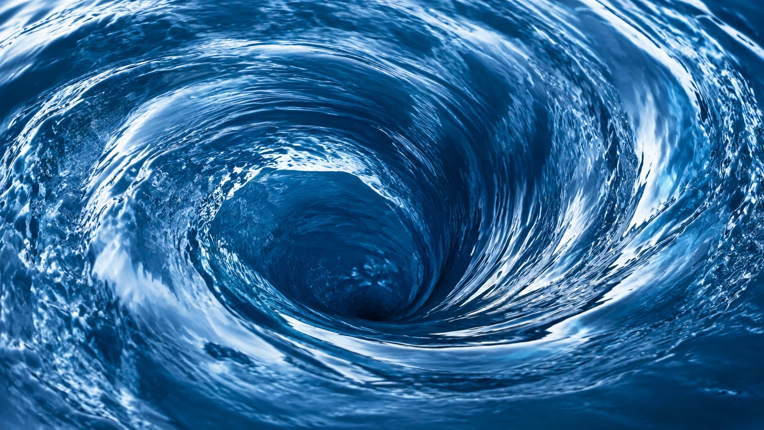
The foundation of vortex flow measurement is the Von Kármán effect. This phenomenon occurs when a fluid—whether liquid or gas—encounters a non-streamlined object, often referred to as a "bluff body" or "shedder bar." As the fluid flows past this obstruction, it cannot follow the sharp contours of the body, causing the flow layers to separate and form alternating swirls or vortices on downstream sides.
These vortices are shed in a staggered, periodic pattern. The frequency at which these vortices are shed is directly proportional to the velocity of the fluid moving through the pipe. Mathematically, this relationship is expressed through the Strouhal number ($St$):
$$f = \frac{St \cdot v}{d}$$
Where:
- $f$ is the vortex shedding frequency.
- $St$ is the Strouhal number (a dimensionless constant for a specific bluff body shape).
- $v$ is the flow velocity.
- $d$ is the width of the bluff body.
Because the shedder bar's width and the Strouhal number remain constant over a wide range of Reynolds numbers, the frequency becomes a highly accurate linear indicator of flow velocity. Modern vortex flowmeters utilize piezoelectric sensors or ultrasonic detectors located behind the shedder bar to count these pressure fluctuations and convert them into a 4-20mA or digital signal.
Key Components of a Vortex Flowmeter
A standard vortex flow measurement system consists of three primary elements:
1. The Meter Body: Typically constructed from stainless steel or high-grade alloys, the body houses the shedder bar and must withstand the process pressure and temperature. It is available in flanged, wafer, or insertion designs.
2. The Shedder Bar: This is the fixed obstruction that generates the vortices. Its geometry is critical; a well-designed shedder bar ensures a stable vortex pattern even at lower velocities.
3. The Sensor and Transmitter: The sensor detects the pressure pulses. Piezoelectric sensors are the most common, as they are robust and can handle extreme temperatures. The transmitter then processes these pulses, applies temperature or pressure compensation (if required), and outputs the flow rate data.
Evaluating Fluid Suitability: Reynolds Number and Viscosity
Before selecting a vortex flowmeter, engineers must evaluate the fluid's physical properties. The most critical factor is the Reynolds Number (Re), which represents the ratio of inertial forces to viscous forces. For a vortex meter to maintain its linear accuracy, the flow must be sufficiently turbulent.
* Linear Range: Most vortex meters require a Reynolds number above 20,000 to maintain standard accuracy (typically ±1% of rate).
* Transitional Range: Between 10,000 and 20,000, the meter may still function, but accuracy decreases.
* Low Reynolds Numbers: Below 10,000, the vortices become too weak to detect reliably, and the relationship between frequency and velocity becomes non-linear.
Viscosity acts as a dampening agent for vortex formation. While vortex flow measurement is excellent for water, chemicals, and steam, it is generally unsuitable for high-viscosity oils or slurries where the viscous forces prevent the formation of distinct vortices.
Practical Selection Table for Industrial Applications
When comparing vortex flow measurement to other common technologies, the following table highlights the strengths and typical use cases:
| Feature | Vortex Flowmeter | Differential Pressure (DP) | Ultrasonic (Transit-Time) |
| :— | :— | :— | :— |
| Primary Media | Steam, Gas, Low-viscosity Liquids | Clean Liquids, Gas, Steam | Clean Liquids, Some Gases |
| Moving Parts | None | None | None |
| Pressure Drop | Low to Moderate | High (due to orifice plate) | Negligible |
| Turndown Ratio | 10:1 to 30:1 | 4:1 to 5:1 | 50:1+ |
| Accuracy | ±0.75% to ±1.5% | ±1% to ±3% | ±0.5% to ±2% |
| Maintenance | Low | Moderate (impulse lines) | Low |
| Temperature Limit | Up to 400°C (752°F) | Varies by seal | Typically < 200°C (392°F) |
Installation Guidelines and Straight Pipe Requirements
The accuracy of vortex flow measurement is highly dependent on the velocity profile of the fluid as it enters the meter. Disturbed flow—caused by elbows, valves, or reducers—can lead to measurement errors or "noise" that the sensor cannot distinguish from actual vortices.
Straight Run Requirements
To ensure a fully developed flow profile, the following minimum straight pipe lengths (expressed in pipe diameters, D) are generally recommended:
* Upstream of Meter:
* Single Elbow: 15D to 20D
* Two Elbows (different planes): 30D to 40D
* Pressure Regulator/Control Valve: 40D to 50D
* Downstream of Meter:
* General requirement: 5D
Orientation and Piping
* Horizontal Pipes: The sensor should ideally be mounted on the side (3 o'clock or 9 o'clock position) if the fluid is steam or high-temperature liquid. This prevents the electronics from being exposed to rising heat or trapped condensate.
* Vertical Pipes: Flow should always be upward when measuring liquids to ensure the pipe remains completely full. For gases and steam, the direction is less critical, provided the pipe is dry.
* Vibration: While modern digital signal processing (DSP) can filter out some mechanical noise, vortex meters should not be installed in areas of extreme pipe vibration. If vibration is unavoidable, pipe supports should be installed immediately upstream and downstream of the meter.
Operational Limitations and Potential Risks
While vortex flow measurement is robust, it is not a "one-size-fits-all" solution. Identifying potential risks early in the project phase can prevent costly downtime.
1. Low-Flow Cutoff: Every vortex meter has a minimum velocity below which it cannot detect vortices. If your process frequently operates at very low flow rates, the meter will read zero, even if fluid is moving.
2. Cavitation: In liquid applications, if the pressure drops too low at the shedder bar, the liquid may vaporize (cavitate). This creates significant noise and can physically erode the meter internals. Always ensure the line pressure is at least 2 to 3 times the pressure drop across the meter.
3. Wet Steam: Vortex meters measure the velocity of the fluid. In steam applications, if the steam is "wet" (contains water droplets), the meter will measure the velocity of the vapor phase but will not account for the mass of the water droplets, leading to significant under-measurement of total energy.
4. Abrasive Fluids: While the shedder bar is stationary, highly abrasive slurries can wear down the sharp edges of the bar over time. This changes the $d$ value in the vortex equation, leading to a gradual drift in calibration.
Frequently Asked Questions (FAQ)
Q: Can vortex flowmeters measure mass flow?
A: Standard vortex meters measure volumetric flow. However, "multivariable" vortex meters include an integrated temperature sensor and pressure transmitter. By knowing the temperature and pressure, the onboard computer can calculate the density of the fluid (especially for steam and gases) and provide a real-time mass flow output.
Q: How often does a vortex flowmeter need calibration?
A: Because there are no moving parts to wear out, the calibration of a vortex meter is exceptionally stable. In clean service, many facilities only perform a verification check every 3 to 5 years. However, if the fluid is corrosive or abrasive, more frequent inspections of the shedder bar are recommended.
Q: What happens if the pipe is not full?
A: For liquid applications, the pipe must be 100% full. If there is air or vapor trapped in the pipe, the vortex shedding pattern will be disrupted, leading to erratic readings or a total loss of signal.
Q: Is it possible to use vortex meters in small pipes?
A: Vortex meters are typically available for pipe sizes from 15 mm (0.5 inches) up to 300 mm (12 inches). For pipes smaller than 15 mm, the physical size of the shedder bar becomes a limiting factor, and other technologies like rotameters or small-bore ultrasonic meters are often preferred.
Conclusion
Vortex flow measurement provides a high-accuracy, low-maintenance solution for a wide variety of industrial fluids. By understanding the necessity of a high Reynolds number and adhering to strict installation guidelines regarding straight pipe runs, engineers can achieve reliable data for years. For those integrating these systems into broader automation frameworks, it is vital to consult with specialists who understand the interplay between flow dynamics and instrument electronics.
To explore specific hardware configurations, technical data sheets, and integrated automation support, you may Review product options and application support to find the right fit for your facility's requirements. Whether managing steam distribution in a chemical plant or monitoring water usage in a treatment facility, the correct application of vortex technology is a cornerstone of modern process efficiency.