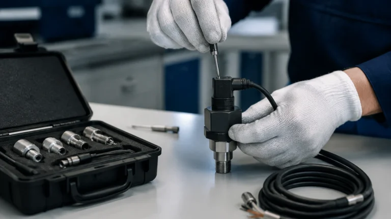
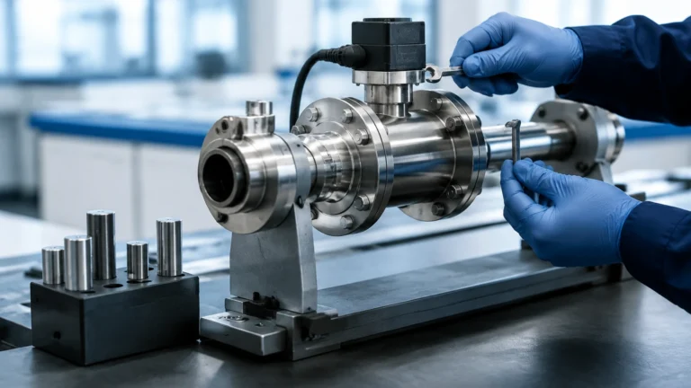
Silo Measurement System
Silo Measurement System
In industrial bulk storage, a silo measurement system is a critical infrastructure component designed to provide real-time visibility into inventory levels. Whether storing cement, grain, plastic pellets, or chemical powders, accurate level monitoring prevents overfills, ensures production continuity, and optimizes supply chain logistics. A modern system integrates advanced sensing technology with data processing units to transform raw distance measurements into actionable volume or mass data.
Selecting the right technology requires a deep understanding of the material characteristics and the physical constraints of the silo environment. From high-dust atmospheres to steep angles of repose, various factors influence the reliability of a silo measurement system. This reference guide examines the fundamental measurement principles, selection criteria, and installation best practices for engineering professionals.
Understanding the Role of a Silo Measurement System
A silo measurement system serves as the "eyes" of a storage facility. Unlike liquid tanks, silos present unique challenges due to the behavior of bulk solids. Materials often form cones (the angle of repose) during filling or craters during discharge, meaning a single point measurement may not always represent the true volume.
Furthermore, the environment inside a silo can be extremely harsh. Dust clouds generated during pneumatic filling can blind optical sensors, while acoustic noise can interfere with ultrasonic pulses. A robust system must account for these variables while providing high-precision data to the facility’s PLC (Programmable Logic Controller) or SCADA system. To explore a comprehensive range of industrial instrumentation, you can visit the Main Page for detailed product specifications.
Core Measurement Principles for Silo Level Monitoring
To choose the correct instrument, it is essential to understand the physics behind the most common sensing technologies used in silo measurement systems.
Non-Contact Radar (Frequency Modulated Continuous Wave – FMCW)
Radar transmitters emit high-frequency electromagnetic pulses (typically 26 GHz or 80 GHz). These pulses reflect off the surface of the material and return to the sensor. The system calculates the distance based on the time-of-flight or frequency shift.
* Advantage: Radar is virtually unaffected by dust, temperature fluctuations, or pressure changes. High-frequency 80 GHz radar offers a narrow beam angle, which is ideal for avoiding internal silo structures like ladders or reinforcements.
Ultrasonic Level Measurement
Ultrasonic sensors emit sound waves that bounce off the material surface. The time taken for the echo to return determines the distance.
* Advantage: Cost-effective and easy to install for shorter silos (under 15 meters).
* Limitation: Performance degrades significantly in heavy dust or high-noise environments, as the sound waves are absorbed or scattered.
Guided Wave Radar (GWR)
GWR uses a cable or rod probe that extends to the bottom of the silo. A low-energy microwave pulse travels along the probe, reflects off the material, and returns.
* Advantage: Extremely accurate and unaffected by dust or vapor. It provides a continuous measurement along the length of the probe.
* Limitation: The probe is subject to mechanical stress from the downward pull of heavy bulk solids (tensile load), which can reach several tons in tall silos.
Hydrostatic Level Transmitters
While primarily used for liquids, hydrostatic sensors measure the pressure exerted by the column of material. In specialized silo applications for slurries or heavy liquids, these transmitters provide reliable data based on the density of the medium.
Practical Selection Table for Silo Level Sensors
Choosing a silo measurement system depends on the specific material and silo geometry. The following table provides a comparison of the most common technologies.
| Technology | Suitable Media | Max Range (Typical) | Dust Resistance | Accuracy | Maintenance |
| :— | :— | :— | :— | :— | :— |
| 80 GHz Radar | Powders, Granules, Pellets | 120 m | Excellent | ±2 mm | Low |
| 26 GHz Radar | Large Granules, Liquids | 30-70 m | Good | ±5 mm | Low |
| Guided Wave Radar | Fine Powders, Solids | 30-60 m | Excellent | ±3 mm | Moderate (Probe wear) |
| Ultrasonic | Non-dusty Solids, Liquids | 15-25 m | Poor | ±0.25% Range | Moderate (Cleaning) |
| Laser | Opaque Solids | 50 m | Fair | ±10 mm | High (Lens cleaning) |
Installation Requirements and Best Practices
The physical installation of a silo measurement system is just as important as the sensor technology itself. Improper placement can lead to "ghost echoes" or inaccurate readings.
1. Beam Path Clearance: For non-contact sensors (Radar and Ultrasonic), the signal beam must have a clear path to the material surface. It should be installed away from the filling stream to prevent the sensor from measuring the falling material instead of the stored inventory.
2. Nozzle Height and Diameter: The mounting nozzle should be kept as short as possible. If the nozzle is too long or narrow, the signal may reflect off the nozzle walls, creating a "near-zone" interference that prevents the sensor from seeing the material when the silo is nearly full.
3. Positioning Relative to the Wall: Sensors should typically be mounted at 1/3 to 1/2 of the silo radius. Mounting too close to the wall can cause signal interference from the silo sides, while mounting exactly in the center may result in inaccurate readings if a deep discharge cone forms.
4. Aiming Flanges: In many silos, the material surface is not flat. Using an adjustable aiming flange allows the sensor to be tilted toward the center of the material's angle of repose, maximizing the strength of the reflected signal.

Overcoming Common Challenges: Dust, Slopes, and Internal Obstacles
Managing Heavy Dust
In industries like cement or flour milling, dust is the primary enemy of a silo measurement system. While 80 GHz radar is the gold standard for penetrating dust, some sensors also incorporate an air purge connection. This allows a small amount of compressed air to keep the sensor face clean, preventing buildup that could attenuate the signal.
Dealing with Internal Structures
Silos often contain internal bracing, ladders, or level switches. These objects can reflect the sensor's signal, leading to false high-level readings. Modern silo measurement systems feature "false echo suppression" software. During commissioning, the user can map the empty silo, allowing the sensor to identify and ignore reflections from fixed internal obstacles.
Accounting for the Angle of Repose
Bulk solids do not level out like liquids. When a silo is filled from the top, a cone forms. When it is emptied from the bottom, a funnel or crater forms. To achieve high accuracy in volume calculations, the system's software must allow for the input of the material’s specific angle of repose. In some critical applications, multiple sensors are used in a single silo to map the surface profile more accurately.
Integration and Data Management
A silo measurement system is rarely a standalone device. It is usually part of a larger automation architecture. Most modern transmitters provide a 4-20mA signal with HART protocol, Modbus RTU, or Profibus. This allows the data to be integrated into a local display for truck drivers or sent to a centralized control room for inventory management.
For remote sites, some systems now offer IoT connectivity, sending level data to the cloud via cellular or LoRaWAN networks. This enables logistics managers to monitor silo levels from a mobile device and schedule refills before a stock-out occurs.
Frequently Asked Questions (FAQ)
Q: Can I use an ultrasonic sensor for a cement silo?
A: It is generally not recommended. The heavy dust generated during the filling of a cement silo absorbs ultrasonic sound waves, leading to signal loss. An 80 GHz non-contact radar is a much more reliable choice for this application.
Q: How do I calculate the weight of the material in my silo?
A: A silo measurement system measures the distance to the surface, which is then converted to volume based on the silo's dimensions. To find the weight, you must multiply the volume by the material's bulk density. Note that bulk density can vary based on how much the material is compacted at the bottom of the silo.
Q: What is the maximum height a radar sensor can measure?
A: High-performance radar transmitters can measure distances up to 120 meters (approximately 393 feet), making them suitable for the tallest industrial silos.
Q: Does the dielectric constant of the material matter?
A: Yes, for radar technology. Materials with a low dielectric constant (like plastic pellets) reflect less energy than materials with a high dielectric constant (like wet grain). However, modern high-sensitivity radar sensors can reliably measure materials with dielectric constants as low as 1.4.
Conclusion
Implementing an effective silo measurement system requires balancing technological capabilities with environmental realities. By understanding the measurement principles of radar, ultrasonic, and guided wave technologies, engineers can select a solution that provides long-term reliability and accuracy. Proper installation, including correct positioning and false echo mapping, ensures that the system provides a true reflection of inventory levels, ultimately improving operational efficiency and safety. For those looking to upgrade their current monitoring capabilities, reviewing available Main Page resources is a recommended first step in identifying the appropriate hardware for specific industrial requirements.