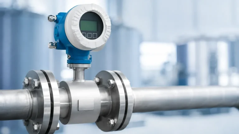
Insertion Mag Meter
Insertion Mag Meter
In the realm of industrial flow measurement, the insertion mag meter represents a versatile and cost-effective solution for monitoring the flow of conductive liquids in large-diameter pipes. Unlike traditional full-bore electromagnetic flow meters, which require a section of the pipeline to be removed and replaced by the meter body, insertion meters are installed through a small hole in the pipe wall. This approach significantly reduces installation costs and downtime, particularly in municipal water systems, HVAC cooling loops, and industrial wastewater applications.
Selecting the right flow measurement technology requires a deep understanding of the fluid dynamics and the specific requirements of the process environment. While Welk is a recognized leader in providing comprehensive Main Page solutions for level measurement, the integration of flow data is often essential for complete industrial automation and process control. This guide explores the engineering principles, selection criteria, and installation best practices for the insertion mag meter.
Understanding the Measurement Principle
The operation of an insertion mag meter is based on Faraday’s Law of Electromagnetic Induction. This physical principle states that a conductor moving through a magnetic field generates an electrical voltage proportional to its velocity. In this application, the conductive liquid flowing through the pipe serves as the moving conductor.
The Physics of Flow Induction
The sensor head of the insertion mag meter contains electromagnetic coils that generate a magnetic field perpendicular to the direction of flow. As the liquid passes through this field, a voltage is induced across a pair of electrodes located on the sensor tip. The relationship is defined by the formula:
E = B × v × L
Where:
* E is the induced voltage.
* B is the magnetic field strength.
* v is the average velocity of the liquid.
* L is the distance between the electrodes.
Because the magnetic field strength and the electrode distance are constant, the induced voltage is directly proportional to the flow velocity. The transmitter then converts this micro-voltage signal into a standard industrial output, such as 4-20mA, pulse, or a digital communication protocol like Modbus or HART.
Point Velocity vs. Volumetric Flow
It is important to note that an insertion mag meter measures "point velocity" at a specific location within the pipe cross-section. To determine the total volumetric flow rate, the device assumes a specific flow profile (typically a fully developed turbulent profile). The accuracy of the measurement depends heavily on the sensor being placed at the correct depth—usually at a point where the local velocity represents the mean velocity of the entire pipe.
Key Advantages in Industrial Applications
For many facility managers and process engineers, the decision to use an insertion mag meter over a full-bore meter is driven by practical constraints and total cost of ownership.
1. Cost-Effectiveness for Large Pipes: As pipe diameters increase (e.g., above DN300 or 12 inches), the cost of a full-bore mag meter rises exponentially due to the weight and material requirements of the flow tube. The cost of an insertion meter remains relatively constant regardless of pipe size.
2. Ease of Installation (Hot Tapping): One of the most significant benefits is the ability to install the meter using a "hot tap" procedure. By using a ball valve and a specialized drilling tool, the sensor can be inserted into a pressurized pipe without shutting down the process or draining the system.
3. Low Pressure Drop: The sensor probe occupies a negligible fraction of the pipe's cross-sectional area, resulting in virtually zero pressure loss compared to mechanical meters or restricted-orifice devices.
4. Versatility: A single probe length can often accommodate a wide range of pipe diameters, making them ideal for facilities with diverse piping infrastructures.
Selection Criteria and Technical Specifications
Choosing the correct insertion mag meter requires evaluating the fluid properties, pipe material, and environmental conditions. The following table provides a general comparison of typical specifications found in industrial-grade units.
| Feature | Typical Specification |
| :— | :— |
| Pipe Size Range | DN50 to DN3000 (2" to 120") |
| Fluid Conductivity | > 5 μS/cm (some models > 20 μS/cm) |
| Accuracy | ±1.0% to ±2.0% of reading |
| Pressure Rating | Up to 16 bar (standard) or 40 bar (high pressure) |
| Fluid Temperature | -20°C to +150°C (depending on seal material) |
| Wetted Materials | 316L Stainless Steel, Hastelloy, PEEK, EPDM |
| Output Signals | 4-20mA, Pulse, RS485 Modbus, HART |
Material Compatibility
The electrodes and the sensor body must be compatible with the process fluid. For general water treatment, 316L stainless steel is standard. However, for corrosive chemicals or brine, electrodes made of Hastelloy C or Tantalum may be required. The insulation material (often PEEK or Teflon) must also withstand the process temperature and pressure.
Fluid Conductivity Requirements
Because the technology relies on electromagnetic induction, the fluid must be electrically conductive. It is not suitable for hydrocarbons (oil, gas), deionized water, or non-polar solvents. Most municipal water and industrial process liquids have sufficient conductivity for reliable measurement.
Installation Guidelines and Best Practices
The accuracy of an insertion mag meter is highly sensitive to the flow profile. If the liquid is swirling or turbulent due to nearby pumps or elbows, the reading will be inconsistent.
Straight Pipe Requirements
To ensure a fully developed flow profile, the sensor must be installed in a straight section of pipe. Standard engineering practice dictates:
* Upstream: At least 10 diameters (10D) of straight pipe after the nearest obstruction (elbows, valves, or pumps).
* Downstream: At least 5 diameters (5D) of straight pipe before the next obstruction.
If these distances cannot be met, the accuracy will degrade, and a full-bore meter or a flow conditioner might be necessary.
Sensor Orientation and Depth
For horizontal pipes, the sensor should ideally be installed at the 3 o'clock or 9 o'clock position. This prevents air bubbles (which collect at the top) or sediment (which settles at the bottom) from interfering with the electrode contact.
Correct insertion depth is critical. For most pipes, the electrodes should be positioned at approximately 1/8th of the pipe diameter or at the center of the pipe, depending on the manufacturer's specific calibration model. Incorrect depth is the most common cause of measurement error in insertion-style meters.
Grounding
To eliminate electrical noise that can interfere with the micro-voltage signal, the meter must be properly grounded to the process fluid. In metal pipes, this is usually achieved by bonding the sensor housing to the pipe. In plastic or lined pipes, grounding rings or extra grounding electrodes are required to establish a stable reference point.

Limitations and Operational Risks
While the insertion mag meter is a powerful tool, it is not a universal solution. Engineers must be aware of the following limitations:
* Sensitivity to Flow Profile: Unlike full-bore meters which average the flow across the entire diameter, insertion meters are "blind" to what is happening on the opposite side of the pipe. If the flow is asymmetrical, the meter will provide an inaccurate reading.
* Lower Accuracy: While high-end full-bore mag meters can reach 0.2% accuracy, insertion meters typically hover around 1% to 2%. This makes them less suitable for high-value custody transfer applications.
* Minimum Velocity: Most mag meters require a minimum flow velocity (typically 0.1 to 0.3 m/s) to generate a detectable voltage. They are not ideal for very low-flow or gravity-fed systems with intermittent flow.
* Debris and Fouling: In wastewater with high solid content, debris can snag on the probe, or grease can coat the electrodes. Regular inspection and cleaning are necessary in "dirty" applications.
Frequently Asked Questions
Q: Can an insertion mag meter measure flow in both directions?
A: Yes, most modern digital transmitters support bi-directional flow measurement, provided the sensor is oriented correctly and the electronics are configured for dual-direction output.
Q: What happens if the pipe is not full?
A: Electromagnetic flow meters require a full pipe to provide an accurate volumetric reading. If the pipe is partially full, the meter will likely over-read the velocity and provide an incorrect total flow. For partially filled pipes, specialized level-area flow meters or radar-based solutions are preferred.
Q: How often does the sensor need calibration?
A: In clean water applications, the calibration is very stable and may only need verification every 2-3 years. In corrosive or abrasive environments, annual checks are recommended to ensure the electrodes have not been damaged or fouled.
Q: Is it possible to use these on plastic pipes?
A: Yes, but grounding is critical. Since plastic is an insulator, you must use grounding rings or ensure the sensor has an integrated grounding electrode to provide a path for electrical noise to dissipate.
Conclusion
The insertion mag meter is an indispensable tool for modern industrial fluid management, offering a balance of performance and economy that full-bore meters cannot match in large-scale piping systems. By adhering to strict installation standards—specifically regarding straight pipe runs and insertion depth—engineers can achieve reliable, repeatable flow data for years of operation.
For organizations looking to optimize their process monitoring, integrating flow data with accurate level measurement is essential. For more information on industrial instrumentation and to explore a wide range of measurement technologies, visit the Welk Main Page to review product options and application support.